Table of Contents
Advertisement
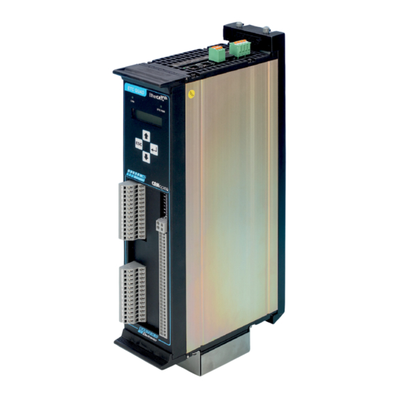
MICROSTEP MOTOR
ETC-QUAD
1902503003
Order Code:
Date: 01/2020 - Rev: 1.2
system-electronics.it
DRIVER
USER MANUAL
UL
1. General characteristics....................................................3
2. Technical specifi cations...................................................3
3. Display and keyboard.....................................................6
4. Axes management Firmware update.................................10
5. Standard drive profi le...................................................12
6. Units of measure for the kinematic parameters...............14
7. WEB interface.............................................................15
8. CANopen interface.......................................................15
9. Installation.................................................................16
10. Power supply sizing...................................................17
11. Connection...............................................................18
12. Available accessories.................................................21
Contents
Advertisement
Table of Contents

Summary of Contents for SYSTEM Electronics ETC-QUAD UL
-
Page 1: Table Of Contents
MICROSTEP MOTOR DRIVER USER MANUAL ETC-QUAD Contents 1. General characteristics............3 2. Technical specifi cations...........3 3. Display and keyboard.............6 4. Axes management Firmware update.........10 5. Standard drive profi le...........12 6. Units of measure for the kinematic parameters....14 7. WEB interface.............15 8. CANopen interface............15 9. Installation..............16 10. Power supply sizing...........17 11. Connection...............18 12. Available accessories..........21 1902503003 Order Code: Date: 01/2020 - Rev: 1.2 system-electronics.it... - Page 2 Revisions Log Pages Rev. 1.2 Drafting 1902503002 ETC-QUAD MICROSTEP MOTOR DRIVER 160V 10A IO_REMOTI UL 1902503003 ETC-QUAD MICROSTEP MOTOR DRIVER 160V 10A MORSETTI UL 2E000002 ETC QUAD TERMINAL DISTRIBUTION BOARD The product meets the EMC protection requirements of Directive 2014/30/ CE (ex 89/336/CEE) and subsequent amendments. SYSTEM CERAMICS SPA Electronics Div. SYSTEM CERAMICS SPA reserves the right to make via Ghiarola Vecchia, 73 changes of any kind to the technical specifications at 41042 Fiorano (MO) - Italy any time without prior notice. The information contained in this document is believed to be correct and reliable.
-
Page 3: General Characteristics
1. General characteristics 2. Technical specifications The Quad Microstep drive unit is designed to control 2.1 Electrical ratings and monitor up to four two-phase stepper motors, operating in bipolar chopper mode. 1. Power Input The drive is equipped with a high performance trajectory Terminal Voltage Current generator and with a digital control system of the +V34-GND (XT2, pin B1,B2,B3,B4) 160Vdc current supplied to ensure smooth and silent motor +V12-GND (XT1, pin B10,B11,B12,B13) - Page 4 • Operating current for each motor max 10A Short Circuit Protection is performed both by Internal continuous (max 13A boost) Solid State Short Circuit Protection and by External Recognized Special-purpose Fuses (recommended) Pro- • Programmable setting of the overvoltage and tection. The fuse has been evaluated during the Short undervoltage threshold to generate a fault Circuit Test also for Branch Circuit Protection. • Cooling fan operated automatically by the drive • Management and reset of faults due to: INTERNAL SOLID STATE SHORT CIRCUIT PROTECTION • Overcurrent between phases of the same motor - The Drive is equipped with Solid State Short Circuit • Overcurrent between phases of different motors Protection. • Short-circuit between phase and power supply EXTERNAL (RECOMMENDED) PROTECTION FUSES – R/C Special-purpose Fuses (JFHR2/JFHR8), manufactured • Short-circuit between phase and GND by COOPER BUSSMANN LLC (E91958), model FWP- • Overtemperature 40B, series FWP, Fuses for protection of semiconductor • Undervoltage / overvoltage.
- Page 5 2.6 Internal Fuse Protection (FU1-FU4) - R/C Fuses, Supplemental (JDYX2,JDYX8), manufactured by HOLLYLAND CO LTD (E156471), model 50CF-100H, filled-tube, rated 10A, 250Vac: Interrupting Rating=1500A, 250Vdc: Interrupting Rating=1000A, Size 5x20mm. Block diagram of internal operation ET1100 Ethercat ETHERCAT CONTROLLER isolated MAGELLAN CP power supply Expansion Ethernet & CAN MICROCONTROLLER MAGELLAN IO Communication for digital inputs and outputs DISPLAY APPLICATION PROGRAM FPGA...
-
Page 6: Display And Keyboard
3. Display and keyboard • Motor dissipator temperature • Controller temperature and supply voltages The drive is equipped with a backlit display and a keypad • Status of jumpers J2..J5 (for testing only during with four buttons for displaying and editing some of the drive production). operating parameters. The display is organized as a set of circular sequences Pressing the Enter key while viewing the default page of pages that can be browsed using the buttons on the makes a new sequence of pages appear (sub-menu): keyboard; these are: • Axes management firmware release • Monitor firmware release • Communication mode (modifiable) To scroll a sequence of pages in the desired •... - Page 7 3.1.2 Digital Inputs 3.1.5 Dissipator temperature status display page display page Digital Inputs T1: 27C T2: 28C 0000000000000000 T3: 27C T4: 24C Displays the instantaneous status of the 16 digital inputs Displays (in degrees Celsius) the internal temperature (from IN_16 to IN_1 reading from left to right) of the power dissipators with an accuracy of ± 3V. N.B.! 1: active input temperatures are not rigidly associated to the 0: inactive input i-th axis; T1 and T2 are two temperatures read inside the only dissipator associated to axes 1 and 2;...
- Page 8 3.2.1 Firmware revision display 3.2.5 CAN communication Speed Display / Setting F/W 5907995102 CAN Open Bit rate Vx.xx 500 Kbps Displays the current revision of the programmed Displays the CAN communication speed and allows to Firmware. modify it. The admitted values are: [10 Kbps] 3.2.2 Monitor revision display [20 Kbps] MON 5907995101 [50 Kbps] Vx.xx [125 Kbps] [250 Kbps] Displays the current revision of the Monitor. [500 Kbps] (<- default) [800 Kbps] 3.2.3 Communication Type Display / [1000 Kbps]...
- Page 9 3.3 Saving the parameters 3.2.7 EtherCAT Address Display / Setting If one has edited the parameters and one presses CANOpen NodeId ESC to go up a level and go back to the main menu, one is prompted whether to save the data permanently. Save Parameters? Displays the EtherCAT node number used and allows to modify it. A CANopen network must not feature two different Using the arrows á...
-
Page 10: Axes Management Firmware Update
3.5 Other diagnostics commands that validate the previously downloaded firmware and force the drive reset; the updated firmware messages will be run upon restart. The various stages of the updating procedure are The following messages appears in the event of an accompanied by relevant messages on the display. error during the detection of the drive boards; it is recommended to contact SYSTEM Electronics. - Page 11 2 - Press the "Invalidate Application" button. 6 - Select the file to be loaded by pressing "Select file" and then "Send". Figure 4.2.2 3 - Wait for the "invalidation ok" message to appear and press the REBOOT button. Figure 4.2.6 7 - Wait for the "download OK" message to appear and press the "VALIDATE FIRMWARE" button. Figure 4.2.3 4 - "RESETTING ..." appears. Figure 4.2.4 Figure 4.2.7 5 - Enter the address again in the Quad EtherCAT IP address bar and press the browser Refresh button At the end, wait for the "validation OK" message to to reload the page properly.
-
Page 12: Standard Drive Profile
5. Standard drive NOTES (1) Bit 15 of the ControlWord (manufacturer profile defined) allows to perform an action similar to that of homing mode 37 if the axis is in halt and in pp mode; the bit is referred to as The ETC840/QUAD drive is a multiple drive (multidrive) "SetPositionOnTheFly"... - Page 13 5.2 “Manufacturer defined” (6) 0=1/256; 1=1/128; … ; 7=1/2; 8=1/1 (full step). objects relating to the individual axes Subindex Name Among the objects defined by System Spa for axes Present Indicates if the limit switch ETC840/QUAD actually implements only those contained is present (=1) or not present (=0) in the following table (relative to axis 1 only); others, although defined, are used mostly for production testing Signal Level...
-
Page 14: Units Of Measure For The Kinematic Parameters
5.3 “Manufacturer defined” (5) Parameters relating to the microprocessor that controls the entire drive. objects relating to the entire (6) The Ti temperatures are not rigidly associated drive to the i-th axis; T1 and T2 are two temperatures read inside the only dissipator associated to axes 1 Among the objects defined by System Spa for the drive and 2;... -
Page 15: Web Interface
8. CANopen interface For example, if one wants to obtain a speed of 50000 microstep/s , one must calculate the following: The drive is equipped with a CAN communication port Acceleration = 50000 microstep/s² and is designed to operate as a CANopen node and it is actually allowed to set (via the front keypad) the 50000 * 65536 = 214 (format 16:16) CANopen communication mode, as well as the CANopen 3906.25² node address, the bit rate (between 10 kbps and 1 The parameters with one jerk dimensions (first derivative Mbps), the insertion of the termination resistor and of acceleration) must be intended as unsigned 32-bit... -
Page 16: Installation
9. Installation 9.1 Inspection Upon receipt of the goods, check that the packaging and the contents are not visibly damaged. Otherwise contact System Electronics. 9.2 Fixing the units The unit is designed for easy mounting on a special rear base (optional for fixing scope only), which can be fixed to any vertical surface by means of a pair of screws (Figure 9.2.1). Figure 9.2.2 Unit insertion 39.5 Figure 9.2.3 Unit removal 34.5 20.5 Figure 9.2.1 Mounting base and dimensions The unit is coupled to the base by means of a series of trapezoidal teeth placed at the upper and lower ends. -
Page 17: Power Supply Sizing
10. Power supply 9.3 Terminal board removal The front panel of the Microstep unit is fitted with the sizing I/O terminal board. The panel and thus all the wiring is easily removable from the unit by simultaneously In order to size the power supply properly, one must leveraging on the two tabs at the ends of the container. carefully assess several factors, such as: the motor The maneuver involves the ejection of the front. used, the number of simultaneous axes one wants to The front is closed by placing the same in its seat move simultaneously, the motor speed and current, the (keeping the tabs open) and then closing the tabs until... -
Page 18: Connection
XP10 POWER 24Vdc - Control board Suggested connection diagram 24V power connector +24Vdc 11. Connections REF 24 11.1 UPPER SIDE TERMINALS connection Max current 0.5A GND: Connect to the ETC1 ETC0 ETH1 +24V REF24 Ethernet ETH1 RJ45 (normally NOT used) This connector features a dust-proof cap. XP10 • 1 Figure 11.1.1 • 2 •... - Page 19 11.2 Front removable Terminal EtherCAT IN (ETC0) • 1 Board connection • 2 Power Section: (numbering starting from the bottom) • 3 • 4 Description Label • 5 PE - Slave Board Grounding • 6 Phase A Motor 4 8 7 6 5 4 3 2 1 •...
- Page 20 11.3 Earth connection 11.5 Front terminal board 1902503003 One must connect all the required terminals to the protective earth (PE): both GR of the front removable I/O Connection terminal board and the GND terminal of the 24V power supply connector XP10. Description REF I/O +24 I/O 11.4 Front terminal board REF I/O 1902503002 +24 I/O REF I/O I/O Connection +24 I/O REF I/O +24 I/O...
-
Page 21: Available Accessories
12. Available Terminals for connection on field Four rows of terminals are envisaged to facilitate the accessories wiring of the sensors and relative power supplies: - Upper row: Inputs connection The following accessories are available for drive code - Second row: Outputs connection 1902503002 to enable input and output terminal - Third row: Reference connection remotation: - Fourth row: 24V power supply connection Board code 2E000002 ETC-QUAD terminal distribution board...
Need help?
Do you have a question about the ETC-QUAD UL and is the answer not in the manual?
Questions and answers