Table of Contents
Advertisement
ESC-0604-04D (6 Circuit, (2) 30 Amp, (0) 10 Amp, (4) 2 Amp)
ESC-0622-04D (6 Circuit, (2) 30 Amp, (2) 10 Amp, (2) 2 Amp)
ESC-0640-04D (6 Circuit, (2) 30 Amp, (4) 10 Amp, (0) 2 Amp)
ESC-0806-04D (8 Circuit, (2) 30 Amp, (0) 10 Amp, (6) 2 Amp)
ESC-0824-04D (8 Circuit, (2) 30 Amp, (2) 10 Amp, (4) 2 Amp)
ESC-0842-04D (8 Circuit, (2) 30 Amp, (4) 10 Amp, (2) 2 Amp)
ESC-0860-04D (8 Circuit, (2) 30 Amp, (6) 10 Amp, (0) 2 Amp)
ESC-1044-04D (10 Circuit, (2) 30 Amp, (4) 10 Amp, (4) 2 Amp)
ESC-1062-04D (10 Circuit, (2) 30 Amp, (6) 10 Amp, (2) 2 Amp)
ESC-1080-04D (10 Circuit, (2) 30 Amp, (8) 10 Amp, (0) 2 Amp)
Read and comply with all instructions, warnings and limitations before
installing, servicing or removing this device.
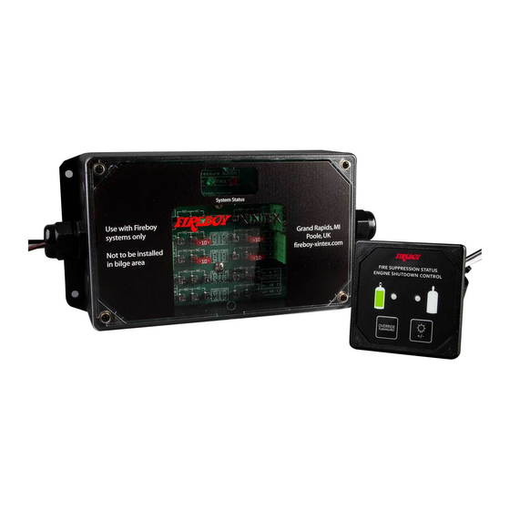
ESC Series
Engine Shutdown Control
Owner's Manual
Installation Instructions
Part Number 18002, G, 09/24/2019
&
1
Advertisement
Table of Contents

Summary of Contents for Fireboy- Xintex ESC Series
- Page 1 ESC Series Engine Shutdown Control ESC-0604-04D (6 Circuit, (2) 30 Amp, (0) 10 Amp, (4) 2 Amp) ESC-0622-04D (6 Circuit, (2) 30 Amp, (2) 10 Amp, (2) 2 Amp) ESC-0640-04D (6 Circuit, (2) 30 Amp, (4) 10 Amp, (0) 2 Amp)
-
Page 2: Table Of Contents
Additional copies of this manual are available at no charge by contacting the manufacturer, distributor or dealer. Fireboy-Xintex reserves the right to change features without notice. General Information Specifications Operation of Fireboy Engine Shutdown/Override System Installation Installing the Engine Shutdown Control Module Installing the Helm Display Unit Electrical Connections Testing the Engine Shutdown System... -
Page 3: General Information
General Information The Fireboy Engine Shutdown Control (ESC) Systems are an effective means to automatically shut down engines, generators, and blower systems in the event of a fire. By shutting down your engine room systems, you will ensure that the fire cannot be fueled by the continued operation of components on the engine as well as maintaining the proper agent concentration needed to extinguish the fire. - Page 4 Specification Continued System Specifications (ESC-0842-04D) Operating Voltage: 9-32 VDC Maximum Current Draw: 188mA @ 12 VDC Operating Temperature: 22°F (-6°C) to 158°F (70°C) Circuits: (2) 30 Amp, (4) 10 Amp, (2) 2 Amp System Specifications (ESC-0860-04D) Operating Voltage: 9-32 VDC Maximum Current Draw: 188mA @ 12 VDC Operating Temperature: 22°F (-6°C) to 158°F (70°C) Circuits: (2) 30 Amp, (6) 10 Amp...
-
Page 5: Operation Of Fireboy Engine Shutdown/Override System
Operation of Fireboy Engine Shutdown/Override System The Fireboy Engine Shutdown Control (ESC) System operates by means of relays. The Shutdown Control Module is connected to the Fireboy Extinguisher by means of the Pressure Switch. When the Pressure Switch opens on the Fireboy Extinguisher, the relays on the Shutdown Control Module activate, disconnecting or connecting power to the connected systems. -
Page 6: Installation
Installation Installing the Engine Shutdown Control Module The Engine Shutdown Control Module should be located near the helm where convenient access to the ignition wiring is available. Use appropriate length #8 screws and secure using all 4 mounting holes. CAUTION: NEVER INSTALL THE ENGINE SHUTDOWN CONTROL MODULE IN A BILGE AREA OR ENGINE ROOM. - Page 7 Connect the Engine Shutdown Control Module’s “V1+” Terminal to a power source through a 2 Amp Breaker. Connect the “Gnd” Terminal to battery ground. The Terminals labeled “Brown”, “White”, and “Black” connect the Helm Display Unit to the Engine Shutdown Control Module. Connectors are provided on each component. Terminals “PS1”...
-
Page 8: Testing The Engine Shutdown System
Testing the Engine Shutdown System The Engine Shutdown System can be tested by disconnecting either wire connection at the Pressure Switch on the Fire Extinguisher. When the wire is disconnected, the engine shutdown will activate. Verify that engines shut down and that all other equipment operates as expected. The Helm Display unit will indicate that the Fire Extinguisher has discharged with a Red LED and audible horn. -
Page 9: Wiring Examples
Wiring Example Part Number 18002, G, 09/24/2019... -
Page 10: Year Limited Warranty
1 Year Limited Warranty This Warranty is in lieu of all other expressed or implied Warranties Seller warrants title, materials, and workmanship on equipment, except components manufactured by others for which the Seller assigns, as permitted, the original manufacturer’s warranty. Seller’s warranty shall be for a period of (1) one year from the date of sale to the ORIGINAL CONSUMER PURCHASER, during which non-conforming equipment returned to the Seller at Buyer’s expense and risk, be repaired or replaced at the Seller’s option.
Need help?
Do you have a question about the ESC Series and is the answer not in the manual?
Questions and answers