
Summary of Contents for Airdach AIDH2400VG1-D
- Page 1 R410A Inverter Split System 17.5 SEER Technical Manual January 2021 Version A-TM-18SS-01...
-
Page 2: Table Of Contents
R410A 17.5 SEER Inverter Split System Technical Manual Content Content Part 1. General Information ..................1 1. Nomenclature ......................... 2 2. Model Names of Indoor/Outdoor Units ............... 4 3. External Appearance ..................... 5 4. Features .......................... 6 Part 2. Indoor Unit ...................... 7 Air Handler Type ...................... -
Page 3: Part 1. General Information
R410A 17.5 SEER Inverter Split System Technical Manual Part 1. General Information 1. Nomenclature…………………………………………….. 2 2. Model Names of Indoor/Outdoor Units………………… 4 3. External Appearance…………………………………….. 6 4. Features…………………………………………………… 6... -
Page 4: Nomenclature
R410A 17.5 SEER Inverter Split System Technical Manual 1. Nomenclature 1.1 Indoor unit... - Page 5 R410A 17.5 SEER Inverter Split System Technical Manual 1.2 Outdoor unit...
-
Page 6: Model Names Of Indoor/Outdoor Units
R410A 17.5 SEER Inverter Split System Technical Manual 2. Model Names of Indoor/Outdoor Units 2.1 Indoor Units Dimension(H×W×D) Model name Power supply (inch) AIDH2400VG1-D 45-3/4 × 19-2/3 × 22 208~230V-1Ph-60Hz AIDH3600VG1-D 45-3/4 × 19-2/3 × 22 208~230V-1Ph-60Hz AIDH4800VG1-D 53 × 22 × 24-1/2... -
Page 7: External Appearance
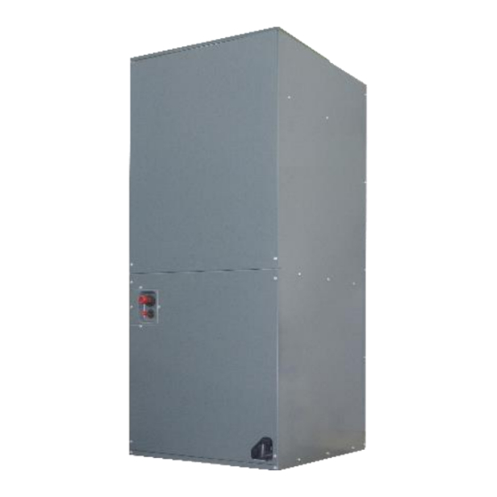
R410A 17.5 SEER Inverter Split System Technical Manual 3. External Appearance 3.1 Indoor unit Air Handler 3.2 Outdoor unit Top-discharge(Metal grill) Note: Standard outdoor unit is using plastic grill. Metal grill can be customized. -
Page 8: Features
R410A 17.5 SEER Inverter Split System Technical Manual 4. Features 4.1 Wide operation range, down to 10°F degree for heating. 4.2 Well-known brand inverter compressor, reliable quality. 4.3 Intelligent defrost programs, unit will choose different defrost program according to real condition. 4.4 Condenser coils constructed with copper tubing and enhanced aluminum fins. -
Page 9: Part 2. Indoor Unit
R410A 17.5 SEER Inverter Split System Technical Manual Part 2. Indoor Unit Air Handler Type 1. Features .................. 8 2. Specification ................9 3. Dimension…………………………………………………………10 4. Service Space ............... 13 5. Wiring Diagrams..............14 6. Electric Characteristics ............14 7. Exploded View ..............15 8. -
Page 10: Features
R410A 17.5 SEER Inverter Split System Technical Manual 1. Features (1) “A” shape coils, constructed with copper tubing and enhanced aluminum fins (2) Direct drive motors,3 speed, provide selections of air flow to meet desired applications. 10” big fan, powerful wind. Motor is covered with thermal insulator, keep motor running in safety status. -
Page 11: Specification
R410A 17.5 SEER Inverter Split System Technical Manual 2. Specification Model AIDH2400VG1-D AIDH3600VG1-D AIDH4800VG1-D AIDH6000VG1-D Power supply V/Ph/Hz 208-230V/1PH/60Hz Capacity Btu/h 24000 34500 47000 56000 Minimum Circuit 17.7 24.2 31.9 36.5 Cooling Ampacity Max. Overcurrent Protection SEER 17.5 17.5 17.5 17.5... -
Page 12: Dimension
R410A 17.5 SEER Inverter Split System Technical Manual 3. Dimension Fig.1 DIMENSIONS DIMENSIONAL DATA Dimensions MODEL UNIT UNIT UNIT SUPPLY LIQUID LINE / SIZE HEIGHT WIDTH LENGTH DUCT "A"/in VAPOR LINE IN "H"/in "W"/in "D"/in 45-3/4 19-2/3 17.87 3/8'' / 7/8'' 45-3/4 19-2/3 17.87... -
Page 13: Service Space
R410A 17.5 SEER Inverter Split System Technical Manual 4. Service Space The indoor unit should be installed in a location that meets the following requirements: INSTALLATION NOTES: 1. Vertical up airflow: For the method of trapping or plugging all drains, see the pic on the left. 2.Horizontal right airflow: For the method of installation, see the pic on the right. -
Page 14: Wiring Diagrams
R410A 17.5 SEER Inverter Split System Technical Manual 5. Wiring Diagrams 24K/36K/48K/60K 6. Electric Characteristics Indoor Units Model Voltage Min. Max. 208-230V 198V 242V AIDC2400NG1-D 208-230V 198V 242V AIDC3600NG1-D 208-230V 198V 242V AIDC4800NG1-D 208-230V 198V 242V AIDC6000NG1-D... -
Page 15: Exploded View
R410A 17.5 SEER Inverter Split System Technical Manual 7. Exploded View Part Name Quantity Filter Cover plate Water pan components 2.1 Water pan# 1 2.2 Water pan# 2 2.3 Water pan fixed block 2.4 Water pan brace Evaporator pre-welded assembly 3.1 Air header Assembly 3.2 Diverter Assembly 3.3 TXV... - Page 16 R410A 17.5 SEER Inverter Split System Technical Manual 3.9 Evaporator Water Baffle #2 3.10 Evaporator Water Baffle #3 3.11 Evaporator Fixing Plate #1 3.12 Evaporator Fixing Plate #2 3.13 Evaporator Junction Plate Chassis assembly Supporter 6.1 Right Volute Wind Wheel 6.2 Indoor Motor Fan Motor Fixing plate assembly 7.1 Fan Motor Fixing plate...
-
Page 17: The Specification Of Wiring
R410A 17.5 SEER Inverter Split System Technical Manual 8. The Specification of Wiring Note: The cross-section areas of wires or lines should not be less than the corresponding ones listed in the table below; Besides, if the power wires is quite long from the unit, please choose the windings with larger cross-section area to guarantee the normal power supply. -
Page 18: Field Wiring
R410A 17.5 SEER Inverter Split System Technical Manual 9. Field Wiring 1. To avoid the electrical shock, please connect the air conditioner with the ground lug. The main power plug in the air conditioner has been joined with the ground wiring, please don't change it freely. -
Page 19: Part 3 Outdoor Unit
R410A 17.5 SEER Inverter Split System Technical Manual Part 3 Outdoor Unit 1. Specification ..............20 2. Dimensions ..............21 3. Service Space..............22 4. Wiring Diagrams ............. 23 5. Electric Characteristics ........... 23 6. Operation Limits .............. 24 7. Sound Levels ..............24 8. -
Page 20: Specification
R410A 17.5 SEER Inverter Split System Technical Manual 1. Specification Model ACTH2418VG1-D ACTH3618VG1-D ACTH4818VG1-D ACTH6018VG1-D Voltage-Phase-Hz V-Ph-Hz 208/230V-1Ph-60Hz Minimum Circuit 17.7 24.2 31.9 36.5 Ampacity Electrical Max. Overcurrent Data Protection Min / Max Volts 187 / 253 187 / 253 187 / 253 187 / 253 Capacity... -
Page 21: Dimensions
R410A 17.5 SEER Inverter Split System Technical Manual 2. Dimensions All dimensions are in inches. They are subject to change without notice. Certified dimensions will be provided upon request. Refrigerant Connection Dimensions (in) Line Size (in) Unit Model Liquid Vapor 29-1/8 29-1/8 0.75... -
Page 22: Service Space
R410A 17.5 SEER Inverter Split System Technical Manual 4. Service Space... -
Page 23: Wiring Diagrams
R410A 17.5 SEER Inverter Split System Technical Manual 4. Wiring Diagrams SEER 17.5 Heat pump 5. Electric Characteristics Outdoor Unit Model Voltage Min. Max. ACTH2418VG1-D 208~230V 187V 253V ACTH3618VG1-D 208~230V 187V 253V ACTH4818VG1-D 208~230V 187V 253V ACTH6018VG1-D 208~230V 187V 253V... -
Page 24: Operation Limits
R410A 17.5 SEER Inverter Split System Technical Manual 6. Operation Limits Operation mode Outdoor temperature ( Room temperature ( Cooling operation 50~118 ≥61 Heating operation 5~75 <86 7. Sound Levels Model Noise level dB(A) ACTH2418VG1-D ACTH3618VG1-D ACTH4818VG1-D ACTH6018VG1-D Note: Sound level is measured at a point 39.37in in front of the unit, at a height of (Unit body height +1)/78.74in. -
Page 25: Exploded View
R410A 17.5 SEER Inverter Split System Technical Manual 8. Exploded View Part Name Quantity Cover net Outdoor motor Axial-flow fan Top cover assembly Support board Piping support plate Refrigerant radiating pipe component Air return duct welding assembly Solenoid Valve Air return duct #1 Air return duct #2 Liquid bypass capillary assembly Solenoid Valve coil... - Page 26 R410A 17.5 SEER Inverter Split System Technical Manual Left side panel Pipeline component 14.1 High pressure valve welding assembly 14.1.1 High pressure valve connecting pipe 14.1.2 S.TL-ZL-FTF-A02 14.2 EXV welding assembly 14.2.1 Connecting pipe #1 14.2.2 Connecting pipe #2 14.2.3 Connecting pipe #3 14.2.4 Check valve...
-
Page 27: Troubleshooting
R410A 17.5 SEER Inverter Split System Technical Manual 9. Troubleshooting 9.1 Compressor driver chip The compressor driver chip controls 2 LED lights, namely red light and green light, and the meaning of the fault light display is as follows: Failure Green light Red light DC bus voltage over/low protection (MCE failure) - Page 28 R410A 17.5 SEER Inverter Split System Technical Manual 9.3 Error code The fault codes for outdoor unit as follows: NO Error Code Status description T4 outdoor ambient temperature sensor fault T5 Discharge temperature sensor fault T3 Outdoor heat exchanger temperature sensor fault AC voltage overvoltage / undervoltage protection EEPROM fault Communication fault of master board and driver chip...
- Page 29 R410A 17.5 SEER Inverter Split System Technical Manual 1. Error code: E4: T4 outdoor ambient temperature sensor fault 2. Error code: E5:T5 Discharge temperature sensor fault...
- Page 30 R410A 17.5 SEER Inverter Split System Technical Manual 3. Error code: E6: T3 Condenser pipe temperature sensor fault (Outlet) 4.Error code: E9: AC voltage overvoltage / undervoltage protection...
- Page 31 R410A 17.5 SEER Inverter Split System Technical Manual 5.Error code: E10: EEPROM error 6.Error code: H0: Communication fault of master board and drive board...
- Page 32 R410A 17.5 SEER Inverter Split System Technical Manual 7.Error code: H4: Display P6 for 3 times within 30 mins (IPM module protection) 8.Error code: H5: Low pressure of system...
- Page 33 R410A 17.5 SEER Inverter Split System Technical Manual 9.Error code: H6:Display P4 for 3 times within 100 minutes (T5 Temp. is too high) 10. Error code: P1: High pressure protection...
- Page 34 R410A 17.5 SEER Inverter Split System Technical Manual 11. Error code: P2: Low pressure protection 12. Error code: P3: Inverter overcurrent protection...
- Page 35 R410A 17.5 SEER Inverter Split System Technical Manual 13.Error code: P4: Exhaust overheating protection 14.Error code: P5:T3 or T3B condenser pipe overheating protection...
- Page 36 R410A 17.5 SEER Inverter Split System Technical Manual 15. Error code: P6: IPM module protection 16. Error code: P9:DC fan motor fault...
- Page 37 R410A 17.5 SEER Inverter Split System Technical Manual 17. Error code: P11:T2 high temperature protection (Heating mode) (1)Works: a) When T2 averages >145°F for a period of time, stop the compressor and display error code P11 for at least 30s; b) When T2 <122°F, the protection is released.
-
Page 38: Part 4 Installation
R410A 17.5 SEER Inverter Split System Technical Manual Part 4 Installation 1 .Precaution on Installation ..........39 2. Vacuum Dry and Leakage Checking ......40 3. Additional Refrigerant Charge ........42 4. Insulation Work ............. 43 5. Test Operation .............. 45... -
Page 39: Precaution On Installation
R410A 17.5 SEER Inverter Split System Technical Manual 1. Precaution on Installation 1.1. Measure the necessary length of the connecting pipe and make it by the following way. Connect the indoor unit at first, then the outdoor unit. Bend the tubing in proper way. Do not harm them. CAUTIONS: ⚫... -
Page 40: Vacuum Dry And Leakage Checking
R410A 17.5 SEER Inverter Split System Technical Manual 2. Vacuum Dry and Leakage Checking 2.1 Vacuum Dry: use vacuum pump to change the moisture (liquid) into steam (gas) in the pipe and discharge it out of the pipe to make the pipe dry. Under one atmospheric pressure, the boiling point of water (steam temperature) is 212°F. - Page 41 R410A 17.5 SEER Inverter Split System Technical Manual ②. Special vacuum dry procedure This vacuum dry method is used in the following conditions: ⚫ ⚫ There’s moisture when flushing the refrigerant pipe. ⚫ Rainwater may enter into the pipe. ⚫ Vacuum dry for the first time ······...
-
Page 42: Additional Refrigerant Charge
R410A 17.5 SEER Inverter Split System Technical Manual 3. Additional Refrigerant Charge Caution ● Refrigerant cannot be charged until field wiring has been completed. ● Refrigerant may only be charged after performing the leak test and the vacuum pumping. ● When charging a system, care shall be taken that its maximum permissible charge is never exceeded, in view of the danger of liquid hammer. -
Page 43: Insulation Work
R410A 17.5 SEER Inverter Split System Technical Manual 4. Insulation Work 4.1 Insulation material and thickness 4.1.1. Insulation material Insulation material should adopt the material which is able to endure the pipe’s temperature: no less than 158°F in the high-pressure side, no less than 248°F in the low-pressure side (For the cooling type machine, no requirements at the low-pressure side.) ◆... - Page 44 R410A 17.5 SEER Inverter Split System Technical Manual For construction convenience, before laying pipes, use insulation material to insulate the pipes to be deal with, at the same time, at two ends of the pipe, remain some length not to be insulated, in order to be welded and check the leakage after laying the pipes.
-
Page 45: Test Operation
R410A 17.5 SEER Inverter Split System Technical Manual 5.Test Operation (1) The test operation must be carried out after the entire installation has been completed. (2) Please confirm the following points before the test operation. ⚫ The indoor unit and outdoor unit are installed properly. ⚫...
Need help?
Do you have a question about the AIDH2400VG1-D and is the answer not in the manual?
Questions and answers