
Summary of Contents for LT LTC-0005A
- Page 1 Zhengzhou Linghang Robot Co.,Ltd Version 21.8 LT Robotic Tool Changer User Manual Product :LTC-0005A...
- Page 2 The content of this document is belong to Zhengzhou Linghang Robot Co.,Ltd (it’s referred to “LT” afterwards), It cannot be copied in part or in whole without the prior written permission of the LT Company. This manual will be revised regularly to reflect and incorporate changes to the product without notice.
-
Page 3: Table Of Contents
Zhengzhou Linghang Robot Co.,Ltd Content Glossary........................1 1.Safety........................4 1.1Notice description..................4 1.2Safety principle.....................5 1.3Notices Rules....................6 2.Product Summary....................7 2.1Master plate assembly................7 2.2Tool plate assembly..................8 2.3Modules......................9 3.Installation....................... 9 3.1Master plate....................11 3.2 Install of master plate................12 3.3Tool plate.....................13 3.4Install of tool plate..................14 3.5Installation diagram of tool plate............. -
Page 4: Glossary
Zhengzhou Linghang Robot Co.,Ltd Glossary Steel ball The steel ring on the tool side,it fits to the locking steel ball during snap ring locking. Circular cam attached to the piston that forces the locking balls outward during the locking process. a wide variety of utility modules that pass electrical power or Electrical electrical signals through Master plate to Tool plate and then to the... - Page 5 Zhengzhou Linghang Robot Co.,Ltd seals the pneumatic chamber and provides mounting points for the Sensor plate Lock/Unlock switches. The half of the Tool Changer to which various tools or end-effector Tool Plate are mounted. Stand that holds Tools not being used by the robot. This is usually Tool stand supplied by the customer and is specific to the application.
- Page 6 Zhengzhou Linghang Robot Co.,Ltd Command that is issued to lock (couple) the Master and Tool Latch Plates. The physical action of the coupling the Master and Tool Plates Lock together. A proximity sensor output signal indicating that the coupling Locked mechanism is in the Locked position.
-
Page 7: Safety
Zhengzhou Linghang Robot Co.,Ltd 1. Safety This section describes the general safety guidelines to be followed for this product,The mentioned warning instructions and safety precautions are applicable to this product. Refer to other application manuals for more specific warning instructions. 1.1 Notices: The following notice is for the products covered by this manual. -
Page 8: Safety Principle
Zhengzhou Linghang Robot Co.,Ltd 1.2 General safety rules Before purchase and installation, the customer shall verify that the selected tool changer has met the maximum allowable moment and allowable torque expected during operation. Please refer to the product specifications in each models of this manual。Special attention Dynamic load caused by acceleration and deceleration of robot.In the case of high acceleration or deceleration, these forces may be many times the static force. -
Page 9: Notices Rules
Zhengzhou Linghang Robot Co.,Ltd 1.3 Safety notes: Warning: do not maintain or repair the tool changer or module , Unless the tool is safely supported or placed on the tool stand , All energized circuits (such as electrical, air, water, etc.) have been closed, the high-voltage connection has been cleaned, and the power supply has been discharged from the circuit in accordance with the customer's safe operation procedures and policies.Personal injury or equipment damage may result if not... -
Page 10: Product Summary
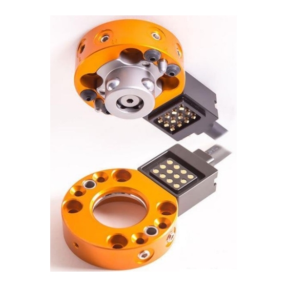
Zhengzhou Linghang Robot Co.,Ltd 2. Product overview The LT robot tool changer enhances the universality of the robot by using a variety of tools (such as fixtures, vacuum suction cups, pneumatic and electric motors, welding guns, etc.). The tool changer includes a master plate installed on the robot arm and a tool plate installed on the customer's tool. -
Page 11: Tool Plate Assembly
Zhengzhou Linghang Robot Co.,Ltd Locating pin Locking ball ball cage Pass port M5 interface Unlock/ Lock M5 interface 2.2 Tool plate components The tool plate components consists of an anodized aluminum body and a hardened stainless steel ball snap ring. Tool plate provides two flat interface for install modules. -
Page 12: Modules
Zhengzhou Linghang Robot Co.,Ltd Steel ball snap ring Aluminum Passport M5 Locating pin hole interface 2.3 Optional modules This model has 1 module mounting interface,can install electrical module, more modules please find from website: https://www.ltautotools.com/ltc-19.html; 3. Installation The end effector is usually connected to the tool plate through the tool adapter flange. - Page 13 Zhengzhou Linghang Robot Co.,Ltd Warning: pneumatic fittings and pipelines must be able to withstand repeated movements of the application without failure. The wiring of electrical and pneumatic lines must minimize the possibility of over stress, pull-out or kink. Failure to do so may result in critical electrical or pneumatic pipeline failure and may result in personal injury or equipment damage.
-
Page 14: Master Plate
Zhengzhou Linghang Robot Co.,Ltd 3.1 Master Plate Master plate usually install on Sixth axis flange of the robot,Master plate match with the size of ISO9409-31.5-4-M5,if the robot Sixth axis fit the size ISO9409-31.5-4-M5can connect directly do not use adapter flange, Otherwise need custom the adapter flange to connect the robot Sixth axis with master plate;The master plate own with a locating pin hole and a locating boss. -
Page 15: Install Of Master Plate
Zhengzhou Linghang Robot Co.,Ltd f.The adapter flange must be firmly installed on the master plate. g.The design of adapter flange must consider the clearance required for module accessories. 3.2 Installation of master plate Tool required:4 mm Allen wrench, torque wrench. Other required:Cleaning cloth,Loctite242 Thread anaerobic adhesive. -
Page 16: Tool Plate
Zhengzhou Linghang Robot Co.,Ltd 3.3Tool plate Tool plate connect to relevant tools.The adapter flange can adapt the tool plate to the corresponding tool. ( Locating pin hole) Accurately position and fix the tool plate to the corresponding tool through the bolt hole. Note: do not use more than two alignment functions when fixing the tool plate to the adapter flange. -
Page 17: Install Of Tool Plate
Zhengzhou Linghang Robot Co.,Ltd 3.4Tool Plate installation Tools Requirements:3 mm Allen wrench, torque wrench. Required items: cleaning cloth, LOCTITE 242 thread anaerobic adhesive. 1、Clean the mounting surface; 2、Install the tooling adapter flange on the customer's tooling, align it with the pin shaft, and fasten it with bolts (coated with LOCTITE 242 glue);Align with the pin shaft and install the tool disc on the adapter flange with M8 screws(Gluing LOCTITE242);... -
Page 18: Install Of Adapter Modules
6、Remove the tool plate; 3.7Optional modules installation Optional modules are usually installed on the tool changer by the LT company before shipment. The following steps described the field installation or removal as required. The tool changer can select many different types of modules. Some modules will require an adapter plate to be installed on the tool changer.(Take... -
Page 19: Module Removal Method
Zhengzhou Linghang Robot Co.,Ltd 6.If fasteners with pre applied adhesive are not used, apply LOCTITE 242 thread sealant to the mounting fasteners; use 2mm Allen wrench and use 4pieces M2.5Install the screw fixing module; 7.Before operation, please remove all protective covers, plugs, tapes, etc. from the module;... - Page 20 Zhengzhou Linghang Robot Co.,Ltd locked or unlocked port on the master plate, the opposite port must be vented to the atmosphere(That is, when air is supplied to the locking port, the unlocking port must be unlocked to the atmosphere) Failure to vent trapped air or vacuum at the inactive port may inhibit the operation of the locking mechanism and prevent locking or unlocking.
-
Page 21: 4、Operation
Zhengzhou Linghang Robot Co.,Ltd 4、Operation The main locking mechanism is pneumatically driven and is locked and unlocked with the bearing seat ring on the tool quick change device. The master plate provides locking/unlocking pressure to the locking mechanism through L/U air ports. -
Page 22: Locking Sequence
Zhengzhou Linghang Robot Co.,Ltd 4.1 Locking sequence Note: The locking mechanism must be in the unlocking position when attempting to connect the tool quick-change device. Failure to comply with this condition may damage tool changer or robot. 1.Please place the master plate right above the tool plate and supply compressed air to the unlock port. -
Page 23: Fault Self Locking Operation
Zhengzhou Linghang Robot Co.,Ltd safe locking position. self locking operation 4.2 Fault When the air pressure on master plste disappears unexpectedly, self-locking function works. After air pressure disappear, master plate and tool plate might has slight seperate, it will cause lock sensors indicate unlocked. fault protection function using multiple CAM to capture bearing of ball and prevent accidental release tool plate, in this case position repeatability can’t keep, and don’t operate tool changers anymore. -
Page 24: Precautions For Tool Placement
Zhengzhou Linghang Robot Co.,Ltd If the tool is released only in a vertical position, the weight of the tool helps unlock. 3. A sufficient delay must be set between solenoid valve propulsion and robot movement to complete the unlocking process and fully release the tool tray before moving the robot. -
Page 25: Maintenance
Zhengzhou Linghang Robot Co.,Ltd starts to move away. If the tool gets stuck on a stand or cannot be released from the robot, the sensor provides a safety measure. The position close to the sensor should be as vertical as possible to prevent metal shavings, weld splashes or other debris from landing on the sensor and producing false readings. -
Page 26: Regular Maintenance
5.1Maintain the checklist regularly Application program Tool change frequency Survey schedule >1 min per week Normal application <1 min per month Welding/servo/deburring, casting operation (dirty per week environment) Check list Install fasteners/adaptor flanges 1、Inspect if fasteners has proper torque,interference and abrasion, tighten and correction as required. -
Page 27: Cleaning And Lubrication Of Locking Mechanism And Locating Pin
Zhengzhou Linghang Robot Co.,Ltd 10、Check hoses for interference, abrasion, cuts and leaks. Replace as needed. 11、Check seal rings for abrasion, cuts and leaks. 12、Inspect electrical contacts/pins for damage, debris and stuck/charred pins. Remove or replace as required. 5.2Cleaning and lubrication of locking mechanism and locating pin Needed goods: Cleaning cloth, Mobil XHP222 extra grade grease 1.Pls put tools in safety place. - Page 28 Zhengzhou Linghang Robot Co.,Ltd 6.Check each ball bearing to ensure it is free to move in the bearing seat ring. Clean up the oil stains on the steel balls and ensure that the steel balls can rotate freely in the rehole. 7.Apply a thick layer of grease to the ball bearings, bearing seat rings and locating pins...
-
Page 29: Inspection And Cleaning Of Electrical Modules
Zhengzhou Linghang Robot Co.,Ltd 8.Thoroughly remove lubricant and debris from bearing seat rings and bushings on tool tray with a clean cleaning cloth. Note: Lubrication is not required on the tool plate assembly. 9.Start for normal operation. 5.3 Inspection and cleaning of electrical modules For details, please refer to 《LTC Electrical Module Instruction Manual》. -
Page 30: Fault Handling
Zhengzhou Linghang Robot Co.,Ltd module. Release pressure and turn off power according to customer specific safety specifications and policies. If no tools are placed and the circuit is powered on, personal injury or device damage may occur. Before performing maintenance or repair on the tool quick-change unit or module, place the tool in the tool holder, close and discharge all energized circuits, clear all pressurized connections, and verify that all circuits are powered off. - Page 31 Zhengzhou Linghang Robot Co.,Ltd Check if tools put in tool support The master plate and tool plate correctly. Reteach robot to make are not in the specified contact master plate closer to tool plate area when trying to lock them. before locking purpose.
- Page 32 Zhengzhou Linghang Robot Co.,Ltd with damage Emergency investigation and treatment 6.1.2Quick tool changers treatment by external interference and impact If the robot or the tool mounted on the robot is disturbed or impacted (impinged) during working, the tool changers must be checked as listed in the table below.
-
Page 33: Air Port Maintenance Process
Zhengzhou Linghang Robot Co.,Ltd plug and surrounding confirm and other electric damage cables with damage modules parts or main body 6.2Air port maintainence process The following services provide instructions for checking, adjustments, tests or replacing of components. 6.2.1 Rubber bushing inspection and replacement Rubber bushing seals the air port from the master plate to the tool plate. - Page 34 Zhengzhou Linghang Robot Co.,Ltd 6.2.2Electric modules sealing inspection and replacement The sealing gasket protects the electrical connection between the master plate module and the tool plate module. Replace the gasket if it is worn or damaged. Refer to LTC electrical module instruction for detailed operations.
-
Page 35: Parameter Table
Zhengzhou Linghang Robot Co.,Ltd 7.Parameter table Master plate LTC-0005AM Model Tool plate LTC-0005AT Payload capacity Locking Force(with air pressure 0.4MPa) 770N load Allowable static moment 13.2Nm Allowable static torque 18Nm Dimension φ46mm Size and precision Combined thickness 30mm Position repeatability ±0.015mm Working Air pressure 0.4~0.7Mpa... -
Page 36: Outline Dimensional Drawing
Zhengzhou Linghang Robot Co.,Ltd 8.Outline Dimension drawing... -
Page 37: Recommended Solenoid Valve To Control Tool Changers
Zhengzhou Linghang Robot Co.,Ltd 9.Recommended Solenoid valve to control tool changers 9.1Single solenoid valve control... -
Page 38: Double Solenoid Valve Control
Zhengzhou Linghang Robot Co.,Ltd 9.2Double solenoid valve control(safer control way) - Page 39 Zhengzhou Linghang Robot Co.,Ltd Thanks! Zhengzhou Linghang Robot Co.,Ltd. Tel:+86 17335767268 Web:www.ltautotools.com mail: info@ltautotools.com...
Need help?
Do you have a question about the LTC-0005A and is the answer not in the manual?
Questions and answers