Table of Contents
Advertisement
Quick Links
Advertisement
Table of Contents

Related Manuals for Vitec Multimedia CellCom 10

Summary of Contents for Vitec Multimedia CellCom 10
- Page 1 CellCom 10 DIGITAL WIRELESS MATRIX I N S T R U C T I O N M A N U A L...
- Page 2 U.S.A Clear-Com is a registered trademark of Vitec Group Communications. The Clear-Com Logo is a registered trademark of Vitec Group Communications. CellCom 10 is a registered trademark of Vitec Group Communications. Eclipse is a registered trademark of Vitec Group Communications.
-
Page 3: Table Of Contents
CellCom 10 Features ......... . . 1-2 A CellCom 10 Communication System......1-3 QUICK START . - Page 4 Overview of the Wireless Belpack ....... . . 6-1 Accessing the Talk Paths on the CellCom 10 Beltpack....6-7 Beltpack Menu Options .
-
Page 5: Important Safety Instructions
IMPORTANT SAFETY INSTRUCTIONS Please read and follow these instructions before operating a CellCom 10 wireless communication system. Keep these instructions for future reference. (1) WARNING: To reduce the risk of fire or electric shock, do not expose this apparatus to rain or moisture. - Page 6 Please familiarize yourself with the safety symbols in Figure 1. When you see these symbols on a CellCom 10 wireless communication system, they warn you of the potential danger of electric shock if the system is used improperly. They also refer you to important operating and maintenance instructions in the manual.
- Page 7 This device complies with Part 15 of the FCC Rules. Operation is subject to the following two conditions: (1) this device may not cause harmful interference, and (2) this device must accept any interference received, including interference that may cause undesired operation. C E L L C O M 1 0 W I R E L E S S C O M M U N I C A T I O N S Y S T E M...
- Page 8 viii C E L L C O M 1 0 W I R E L E S S C O M M U N I C A T I O N S Y S T E M...
-
Page 9: Getting Started: An Introduction To Cellcom 10
GETTING STARTED: AN INTRODUCTION TO CELLCOM 10 With a CellCom 10 wireless beltpack you can roam freely around a studio or production facility while talking and listening to all, or selected, members of the production team. With its six communication routes, the beltpack gives you the flexibility to communicate quickly and seamlessly with individuals or groups, and to change communication routes as often as needed. -
Page 10: Cellcom 10 Features
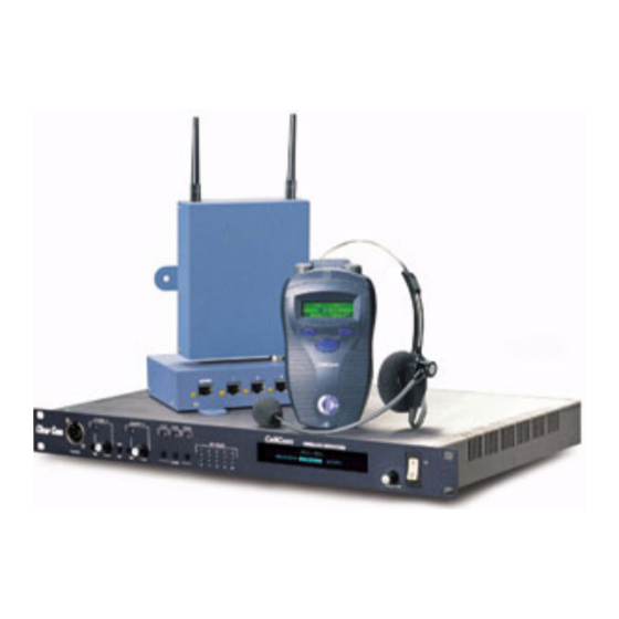
Figure 2: A CellCom 10 Digital Wireless Communication System 1 - 2 C E L L C O M 1 0 W I R E L E S S C O M M U N I C A T I O N S Y S T E M... -
Page 11: A Cellcom 10 Communication System
A CELLCOM 10 COMMUNICATION SYSTEM A CellCom 10 system consists of three basic elements: • The wireless beltpacks. • The base station that routes communication to and from wireless beltpacks and other audio devices. • The transceiver/antennas that provide custom coverage zones in which four to five beltpacks can operate. - Page 12 CellCom 10 base station to the first, creating a 20-beltpack system. Figure 3 illustrates how a CellCom 10 system can be set up to operate in a single studio or in a large-scale permanent broadcast facility.
-
Page 13: Quick Start
To complete the exercise, you will need the following equipment.The goal is to establish communication between these devices: • A CellCom 10 system including two wireless beltpacks, an antenna, and a base station. • A 4-wire audio source, such as an Eclipse matrix. - Page 14 CellCom 10 Base Station Rear Panel Figure 1: Connect the CellCom Base Station to the Wired Devices 5. To get the CellCom 10 into a “clean” state for the example below, from the base station’s front-panel display, scroll to and select PORTS, then 4WIR1, then CALLS, then NONE.
- Page 15 6. Enable the party line by pressing the CH A enable button on the base staton’s front panel until the CH A enable light illuminates. (See Figure 2.) Be aware that a loud tone is generated in the party-line beltpack’s headset when it is first enabled from the front panel.
- Page 16 ASSIGNING LABELS TO THE CELLCOM BELTPACKS To assign a name (“label”) to CellCom beltpack #1: 1. From the base station’s front-panel display, use the setup/enter knob to select BELTPACKS, then BPK01, and then LABEL. Rotate the setup/enter knob until the desired item is highlighted. Press the knob in to select the item.
- Page 17 ASSIGNING THE GROUP LABEL TO CELLCOM BELT- PACK KEYS You will now assign the group label you created in the prevous step, GP#01, to the first key of each of the CellCom wireless beltpacks. To assign the group label to the first key of CellCom beltpack #1: 1.
- Page 18 • Examine wireless beltpack #2. If it is on page #1, the green (listen) light should be flashing, and you should be able to hear audio from beltpack #1. At this point, beltpack #1 won’t be able to hear audio from beltpack #2. 3.
- Page 19 • Audio from the 4-wire audio device will be audible from the wired beltpack’s headset. 3. If the base unit is powered down and then up again, the talk paths from the wired beltpack (on party-line channel A) are re-established to the 4-wire device and to the two wireless beltpacks.
- Page 20 2 - 8 C E L L C O M 1 0 W I R E L E S S C O M M U N I C A T I O N S Y S T E M...
-
Page 21: Introduction
OPERATING THE CELLCOM 10 BASE STATION INTRODUCTION The CellCom 10 base station provides all of the intelligence and signal routing for the CellCom 10 digital wireless intercom system. The base station is effectively a full-duplex digital matrix communications system, with virtual “ports”... - Page 22 Channel A Talk Switch and Light/Listen Level Knob The channel A talk switch and associated light, and listen level knob, allow full-duplex conversations with any CellCom 10 wireless beltpacks or other communications systems wired to the rear of the base station to which the onboard Channel A has been assigned.
- Page 23 The display screen shows all of the menus and programming options that are available within the CellCom 10 system. The user can select a particular beltpack and view all of its current talk/listen assignments, or see all of the current members of a particular group.
- Page 24 3 - 4 C E L L C O M 1 0 W I R E L E S S C O M M U N I C A T I O N S Y S T E M...
-
Page 25: Understanding The Back-Panel Connectors
CONNECTING THE CELLCOM 10 BASE STATION The CellCom 10 base station connects to the following wired interfaces through its rear-panel connectors: • Base station to AC power The CellCom 10 base station connects to several • Base station to party-line channels A and B wired interfaces that can •... - Page 26 Party Line Channel A Connectors The CellCom 10 base station provides two pairs of party-line connectors, labeled “Channel A” and “Channel B.” Each pair of female and male 3-pin XLR connectors joins a channel of party-line intercom to the CellCom 10, allowing communication between the wired party-line equipment and CellCom 10 wireless beltpacks.
- Page 27 Level adjustment is done via the front-panel display programming. Base Loop Connector You use the base loop RJ-45 connector to join two CellCom 10 base stations to form one larger communications system, with up to 20 wireless beltpacks. The wired connection passes the digital audio signals and time slot data between the two bases.
-
Page 28: Connecting To Party-Line Intercom Systems
CONNECTING TO PARTY-LINE INTERCOM SYSTEMS Up to two channels of party-line intercom can be connected to the CellCom 10 base station. The descriptions below will discuss connections with Clear-Com and compatible party-line, RTS party-line, the ability of CellCom 10 to power a few Clear-Com beltpacks by itself, and the front-panel settings associated with these party-line connections. - Page 29 Warning: Previous versions of this manual described a cable which would allow you to access channel 1 of a dual channel RTS beltpack. DO NOT attempt to use a cable like this as it could result in damage to your CellCom 10 base unit. FRONT-PANEL ADJUSTMENTS FOR PARTY-LINE CONNECTIONS To connect the party-line channels to CellCom 10 and make the communication available to the rest of the system, press the CH-A and/or CH-B enable switches.
-
Page 30: Connecting To 4-Wire And Digital Matrix Intercom
INTERCOM Up to four channels of 4-wire/digital matrix intercom can be connected to the CellCom 10 base. The descriptions below will discuss connections with Clear-Com Matrix Plus digital matrix, Clear-Com Eclipse digital matrix, other brands of digital matrix intercoms, other 4-wire audio devices, and the front-panel settings associated with these 4-wire connections. - Page 31 CEL-BASE base station 4-wire port to “4-Wire.” If you will be putting the label of this CellCom 10 4-wire port onto more than one intercom panel within the matrix system, and you want to allow any and all people who...
- Page 32 CellCom 10 beltpacks. The audio output side of the CellCom 10 4-wire connectors could be used to route a CellCom 10 wireless beltpack user’s voice out of the system for paging or other reasons, similar to the SA OUT connector.
-
Page 33: Connecting To A Program Audio Source
CONNECTING TO A PROGRAM AUDIO SOURCE CellCom 10 can connect with a program audio source, making it accessible to be assigned by itself to a communication path to one or more CEL-BP wireless beltpacks, or to be added to a group with other communications and assigned to beltpacks. -
Page 34: Connecting To A Pc
CONNECTING TO A PC CONNECTING VIA THE SERIAL PORT The PC serial port on the rear of the CellCom 10 base station is mainly used for firmware version upgrades of the system. A specially wired cable is required for these updates, consisting of two 9-pin D-type connectors for the PC and the CellCom 10 ends. -
Page 35: Linking Two Base Stations To Form Larger Systems
LINKING TWO BASE STATIONS TO FORM LARGER SYSTEMS Two CellCom 10 base stations may be joined via the rear-panel BASE LOOP connection to create larger communications systems that will support up to 20 wireless beltpacks, plus all of the available rear-panel connected devices on both bases. - Page 36 CEL-TA transceiver antennas can be located from the base to beyond 1,000 meters (3,200 feet). For example, a splitter can be used to connect to a CellCom 10 base that is located in a production truck outside an arena or stadium, with a single CAT-5 cable going to the splitter which is then located just inside the stadium.
- Page 37 POWERING AN ANTENNA OR ANTENNA SPLITTER You provide 24 VDC power to a CellCom 10 antenna in one of three ways: • Connect the antenna to a 150/UNI-DIN power supply unit through the 4-pin DIN connector at the antenna. • Connect the antenna to an antenna splitter which is powered by a power-supply unit.
- Page 38 4 - 1 4 C E L L C O M 1 0 W I R E L E S S C O M M U N I C A T I O N S Y S T E M...
-
Page 39: Programming A System From The Base Station
PROGRAMMING A SYSTEM FROM THE BASE STATION You program a CellCom 10 system using the menus displayed on the base station’s front panel. Programming the system requires four basic steps: You program a system using 1. Create individual names (“labels”) for the wireless beltpacks and for the the menus displayed on the wired devices connected to the base station. -
Page 40: Using The Base Station's Programming Menus
CREATING BELTPACK LABELS The first step in creating a CellCom 10 system is to create individual names (“labels”) for the wireless beltpacks and for the wired devices connected to the base station. You use individual labels for building “point-to-point”... - Page 41 Note: A beltpack’s generic name appears on the upper row, while the name you give it appears on the lower row. • The beltpacks’ generic labels BPK01 through BPK05 appear on the upper row, while the labels you give the beltpacks appear just under the generic You use individual labels for labels.
-
Page 42: Creating Port Labels
If you wish to edit another beltpack label, scroll clockwise to the BACK command and select it. The AVAILABLE BELTPACKS screen appears. Select a new beltpack label to edit, and repeat steps 2 through 9. CREATING PORT LABELS Port labels identify the You create port labels to identify the audio devices wired to the base station’s rear devices wired to the base panel ports, such as party-line beltpacks, 4-wire devices, program sources, and... -
Page 43: Creating Group Labels
A menu to edit that port’s label appears as shown in Figure 8. HDSTA V I D E Figure 8: Editing a Port’s Label 4. Scroll to and select the alphanumeric character you wish to change. A box appears around the character. The upper label retains the 5. - Page 44 By scrolling all the way to the right, and then continuing to scroll, GP#06 through GP#10 appear on the second page of the menu. AVAILABLE GROUPS GP 01 GP 03 GP 02 GP 04 GP 05 BACK AUDIO GP02 GP01 GP03 GP04 Figure 9: Select a group label from the AVAILABLE GROUPS menu...
-
Page 45: Adding Group Members
The MEMBERS menu appears, as shown in Figure 13. On this set of pages, all of the base-station wired ports appear (HDSTA through STGAN, “headset A” through “stage announce”), followed by the labels for all ten CellCom 10 beltpacks. EDITING MEMBERS OF GP01--AUDIO... -
Page 46: Assigning Labels To Beltpacks Keys
7. Your changes are saved and applied automatically five seconds after the last time you press or turn the setup/enter knob. The front-panel display flashes to indicate that the changes are being saved and applied. To edit a group that already has members, go through the procedure above to reach the member labels. - Page 47 Figure 15 shows how the front-panel screen on a beltpack displays its six communications routes. BELTPACK FRONT-PANEL DISPLAY SCREEN Talk B Assignments Talk A Assignments Page 1 - Assignment 1 Page 1 - Assignment 2 Page 2 - Assignment 1 Page 2 - Assignment 2 Page 3 - Assignment 2 Page 3 - Assignment 1...
-
Page 48: Setting Input And Output Audio Levels
BELTPACKS menu. Highlight and select the next beltpack, and repeat the above procedures. SETTING INPUT AND OUTPUT AUDIO LEVELS The settings at the base station determine the input and output audio levels of a device connected to a port. You can adjust the levels from -20 to +18 dB. •... -
Page 49: Base Station System Menu
The base station automatically sets the port’s termination, gain, and call signalling options for the selected party line type. BASE STATION SYSTEM MENU The base station SYSTEM menu offers several system-wide capabilities, including giving you information on firmware, DECT system ID, IP address, and active antenna status, in addition to setting overall system gain, locking the front-panel enable buttons, and restoring the most recent downloaded configuration. - Page 50 “__” indicates an empty slot on an acive antenna that is connected to the base station. A number in place of a “__” indicates that this slot is occupied by the indicated beltpack. Blank spaces next to an antenna number indicate that no antenna has been detected in this position.
-
Page 51: Overview Of The Wireless Belpack
Figure 1: Overview of Beltpack Functions A CellCom 10 wireless beltpack gives you simultaneous access to six channels of talk/listen communication, with the ability to switch among them as desired. Any or all of these six routes may be kept open during use. Incoming volume levels (“listen levels”) may be individually adjusted using the two push-to-talk... - Page 52 A 4-pin male headset connector is provided for connection with a standard Clear-Com headset or similar. The CellCom 10 beltpack will operate for up to 8 hours on four AA alkaline or rechargeable NiMH batteries.
- Page 53 Talk/Listen Lights, Channels A and B The green “listen” light blinks whenever a beltpack receives audio from a source whose label is displayed on the beltpack’s LED screen. When you press the talk button to “talk,” the green light then illuminates steadily and the red light also illuminates.
- Page 54 Figure 4: View of Back of Beltpack Power Button The recessed power button is used to turn the CellCom 10 beltpack on and off. Press and hold the button for about three seconds to turn the unit on. To turn the unit off, again press and hold the button for about three seconds.
- Page 55 Battery Recharger Connector The CellCom 10 beltpack features an internal battery charger when you insert four AA-format NiMH batteries to power the unit. The recharger circuit includes a thermistor that senses the temperature of the battery pack to prevent overcharging.
- Page 56 After pressing the POWER button on the rear of the beltpack for approximately three seconds, the top control panel LEDs will flash and the display will light. The display will say “CellCom 10” and “Searching for Network.” It will briefly say “Getting Roles,” and then will go to the main user screen.
- Page 57 REMOVING REGISTERED BELTPACKS FROM THE BASE STATION Beltpacks can be removed from the base station and new ones substituted with the CellCom 10 Toolkit program. Refer to the CellCom 10 Toolkit User Guide for more information. ACCESSING THE TALK PATHS ON THE CELLCOM 10 BELTPACK You can access up to six communications routes with a beltpack.
- Page 58 • Page two shows the next set of assignments for the Talk A and Talk B buttons (2 assignments). • Page three shows the next set of assignments for the Talk A and Talk B knobs (2 assignments). Figure 6 shows how the front-panel screen on a beltpack displays its six communications routes.
- Page 59 SETTING AND ADJUSTING LISTEN LEVELS You can adjust a beltpack’s incoming audio volume (“listen level”) in two ways: • You can set the overall maximum level for the beltpack by using the beltpack menu options. • You can adjust the incoming audio level as you talk or listen on the beltpack using the beltpack’s talk buttons.
-
Page 60: Beltpack Menu Options
BELTPACK MENU OPTIONS The CellCom 10 beltpack presents you with a number of adjustable parameters. The main categories of the adjustments are: Alarm Options, Audio Options, View Status, and Adjust Contrast. An icon of an upward pointing arrow designates EXIT or BACK, and is available on each menu page. - Page 61 • When you select ON, you will hear a beeping in the beltpack’s headset when the beltpack is almost out of the range of the antenna, and will soon lose connection with the system. When the beltpack’s signal-level icon is at the second-lowest increment, you will hear two quick beeps at approximately one-second intervals in the headset.
- Page 62 Beltpack ID Beltpack ID, also known as IPEI, gives the unique identification number for the transceiver in the CellCom 10 beltpack. RF Carrier Mask The RF carrier mask tells the base station and beltpacks which of the standard DECT carrier frequencies to use.
- Page 63 Carrier Number and Slot that the beltpack is currently using (this can dynamically change as needed during use). In addition, the Received Signal Strength Indication (RSSI) is numerically indicated, with 55 being the highest value; also, the error percentage is shown. Adjust Contrast Adjust Contrast provides a slide bar going from “-“to “+”, allowing the user to adjust the contrast on the display.
- Page 64 6 - 1 4 C E L L C O M 1 0 W I R E L E S S C O M M U N I C A T I O N S Y S T E M...
-
Page 65: Transceiver/Antenna
Each CEL-TA is connected to the CellCom 10 base, either directly or via a CEL-SP splitter. The unit has two flanges on the rear side that permit the unit to be screwed or otherwise attached to surfaces. - Page 66 Matrix Connector This RJ-45 connector is used to connect the bi-directional signal from the CellCom 10 base, directly or via the splitter. Up to 1,000 meters of 4-pair CAT-5 cable can be used for this connection between base and transceiver/antenna.
- Page 67 CellCom 10 base or splitter. In larger systems – approaching 20 beltpacks – it is wiser to allow one transceiver/antenna for every 3 to 4 users to ensure smooth handoffs between transceiver/antennas.
-
Page 68: Transceiver/Antenna Splitter
TRANSCEIVER/ANTENNA SPLITTER (CEL-SP) The CEL-SP antenna splitter is the device that connects multiple transceiver/antennas to the CellCom 10 base station. It has an RJ-45 connector that carries the data between a base transceiver port and the splitter, and five RJ-45 connectors to feed that information to and from up to five antennas. The splitter is always locally powered via the supplied external in-line universal power supply. - Page 69 This yellow light indicates that the CEL-SP splitter is receiving data from the CellCom 10 base. Matrix (CellCom 10 Base) Connector This RJ-45 connector accepts a 4-pair data cable from the CellCom 10 base station transceiver port. This cable can be up to 1,000 meters in length. Splitter-to-Transceiver/Antenna Signal Indicator Light These yellow lights indicate that a connection from the CellCom 10 base is available to the particular transceiver connected to that port.
- Page 70 This male DB-15 connector is reserved for future use. EXP OUT Connector This female DB-15 connector is reserved for future use. CONNECTING AN ANTENNA SPLITTER TO THE CELLCOM 10 BASE AND TO TRANSCEIVER/ANTENNAS After the connections have been made between the splitter and the transceiver/antennas, make sure that the data LED’s are lit at the individual ports...
-
Page 71: Installing A System
INSTALLING A SYSTEM You can begin using a CellCom 10 system as soon as you receive it, as long as the beltpacks are registered to the base, using the generic user labels for the beltpacks and the rear-panel connections. PLACING THE BASE STATION The first stage in setup is placing the base station in a convenient location, knowing that it is the central routing unit of the CellCom 10 system. - Page 72 WIRING THE ANTENNAS AND SPLITTERS To wire antennas and splitters: 1. Run 4-pair CAT-5 cable from the CellCom 10 base to the antenna or splitter, and determine that the antenna or splitter is showing both power (green LED lit) and signal (yellow LED lit when the base station is on).
-
Page 73: Doing A Site Survey To Determine Coverage Areas
DOING A SITE SURVEY TO DETERMINE COVERAGE AREAS Some CellCom 10 users may want to test coverage areas more extensively before setting up a a complete system. Testing a system in the setting in which it will be located helps you to set up the system successfully to meet your needs. Factors in the local setting may affect the areas a system can cover, so it is important to plan a site setup accordingly. - Page 74 The signal strength is shown in the Received Signal Strength Indication (RSSI) field in the leftmost lower corner of the beltpack’s display. The error rate is shown in the ERR field in the middle of the display. RPN field shows the antenna that the beltpack is connected to.
- Page 75 7. You will need to adjust antenna placement to get the best coverage. Zone C Zone A Zone B 1 User 4 Users 5 Users Figure 2: Mapping overlapping coverage zones TESTING ANTENNA HANDOFF After you test the coverage areas for individual antennas, test the handoff between the antennas.
- Page 76 on each antenna that are occupied by beltpacks. This information may be useful during a site survey, or when troubleshooting coverage areas or antenna connections. A typical display is shown below: ANTNS MENU 1/ __ __ __ __ __ 6/ 1 __ __ __ __ BACK 2/ __ __ __ __ __ 7/ 3 __ __ __ __...
- Page 77 antenna. Similarly, for good coverage for nine or more beltpacks simultaneously, a third antenna may be required. CONDITIONS AFFECTING COVERAGE AREAS The environment in which a system is located affects the coverage area for any particular beltpack/antenna combination. The presence of walls, floors, ceilings, trees, shrubbery, people, and numerous other items may affect the coverage zone.
- Page 78 8 - 8 C E L L C O M 1 0 W I R E L E S S C O M M U N I C A T I O N S Y S T E M...
-
Page 79: Specifications
SPECIFICATIONS CellCom 10 CEL-BASE Base Station Base-to-Beltpack Frequency Response 100 Hz – 7.1 kHz Number of CEL-BP Beltpacks per Base Station Number of CEL-TA Transceiver/ Antennas Supported by Base: Number of Transceiver/Antenna Ports Number of Base Loop Ports 1 (combines 2 bases into one... - Page 80 1-RU unit, 44 x 483 x 312 mm (hwd) (1.75 x 19.0 x 12.5 inches) Weight Approx. 10 lb. CellCom 10 CEL-BP Beltpack Beltpack Frequency Response 100 Hz – 7.1 kHz Beltpack Assignment-Select Buttons 3, used to scroll and select talk/listen “pages”...
- Page 81 Via 24VDC power supply Range per CEL-TA Transceiver/Antenna 150 m from transceiver/antenna ideal, line-of-sight conditions; 50 m indoors; use multiple CEL-TAs for larger, custom coverage areas Connection to CellCom 10 Base RJ-45 Mounting Via integral tabs with holes for screws Dimensions 38 x 125 x 153 mm (dwh) (1.5 x 5.0 x 6.1 inches)
- Page 82 Dynamic allocation of frequencies and handoff of beltpacks among the transceiver/antennas up to their individual limit of 5 connected beltpacks at a time; each beltpack is assigned a “virtual port” within the CellCom 10 base. 9 - 4 C E L L C O M 1 0 W I R E L E S S C O M M U N I C A T I O N S Y S T E M...
-
Page 83: Appendix 1: Dect Carrier Frequency Chart
APPENDIX 1: DECT CARRIER FREQUENCY CHART CARRIER FREQUENCY CARRIER FREQUENCY 1897.344 1911.168 1895.616 1912.896 1893.888 1914.624 1892.160 1916.352 1890.432 1918.080 1888.704 1919.808 1886.976 1921.536 1885.248 1923.264 1883.520 1924.992 1881.972 1926.720 1899.072 1928.448 1900.800 1930.176 1902.528 1931.904 1904.256 1933.632 1905.984 1907.712 1909.440 * Carriers 23 through 27 are those used in the USA. - Page 84 1 0 - 2 C E L L C O M 1 0 W I R E L E S S C O M M U N I C A T I O N S Y S T E M...
-
Page 85: Appendix 2: Overview Of Programming Menus
APPENDIX 2: OVERVIEW OF PROGRAMMING MENUS 1 1 - 1 C E L L C O M 1 0 W I R E L E S S C O M M U N I C A T I O N S Y S T E M... - Page 86 1 1 - 2 C E L L C O M 1 0 W I R E L E S S C O M M U N I C A T I O N S Y S T E M...
-
Page 87: Technical Support
WARRANTY Clear-Com guarantees this product to be free of manufacturing defects in material and workmanship under normal use for a period of two years from the date of purchase. TECHNICAL SUPPORT To ensure complete and timely support to its customers, Clear-Com maintains Technical Service Centers (TSC) staffed by qualified technical personnel. -
Page 88: Non-Warranty Repairs
Replaceable Unit (LRU) that is returned to Clear-Com during the warranty period. A Line Replaceable Unit (LRU) is defined as: an assembly that can be safely removed from the system and readily replaced by plugging in a new unit. In the case of ancillary items such as power supplies, the entire power supply would be returned. - Page 89 thereof delivered hereunder, or any other warranties or guarantees, including but not limited to any liability of Clear-Com for any consequential and/or incidental damages and/or losses (including loss of use, revenue, and/or profits). In any event, the maximum extent of Clear-Com’s liability to customer hereunder shall not under any circumstances exceed the cost of repairing or replacing any part(s) fount to be defective within the warranty period as aforesaid.
- Page 90 1 2 - 4 W A R R A N T Y...
Need help?
Do you have a question about the CellCom 10 and is the answer not in the manual?
Questions and answers