Table of Contents
Advertisement
Quick Links
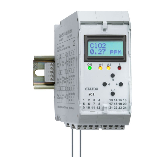
Statox 503 Control Module
Getting started with the Statox 503 Control Module
Safety notes
Read and observe this manual prior to installation and start-up.
The Statox 503 Control Module must not be operated out of the specified ambient conditions (see
Technical Data). In particular, it must not be operated in classified areas!
The Statox 503 Control Module must be operated, maintained and repaired exclusively by trained and
authorized personnel. Use only Compur Monitors original parts for repair and maintenance.
Do not connect the module directly to mains!
Do not modify the product. Do not use if damaged or incomplete.
When installing this product observe all local standards and regulations.
Disregarding of the above instructions may cause danger to people and property.
Product description
The Statox 503 Control Module operates together with 4-20 mA transmitters and the complete range of Statox 501
sensor heads. It provides a 4-20 mA analog output, 3 alarm relays, a display and LEDs for visible alarms. It can also
be operated as Common Alarm Module collecting alarm signals via communication bus.
Power
supply
24 VDC
Control Module, Art.# 555500
Control Module, Art.# 555500, configured as Common Alarm Module
Figure 1: Requirements for bus operation, sample installation
Issue 9/2018
This document is for your first information!
Detailed manuals in several languages are available on
our homepage www.compur.com
Set with 2 bus adapters, mandatory
required for each module in bus
operation, art.# 557002
Connection set for bus adapter
(Bus plug left and right),
optional, art.# 557003
DIN rail TS 35
Page 1 of 10
Advertisement
Table of Contents

Related Manuals for Compur Statox 503

Summary of Contents for Compur Statox 503
- Page 1 Product description The Statox 503 Control Module operates together with 4-20 mA transmitters and the complete range of Statox 501 sensor heads. It provides a 4-20 mA analog output, 3 alarm relays, a display and LEDs for visible alarms. It can also be operated as Common Alarm Module collecting alarm signals via communication bus.
-
Page 2: Mounting And Dismounting
There are two options connecting the 24 VDC power supply: via bus plug to the communication bus or directly to the relevant Statox 503 Control Module terminal. In both cases all subsequent modules are automatically connected to the power supply via bus. The terminals are rated to accept a max. diameter of 2,5 mm... -
Page 3: Main Menu Structure
Statox 503 Control Module Main menu structure Push ◄- and ► -button together for 2 s. Select each digit of the password 1994 with the arrow keys and confirm with ENTER. Correct false inputs with the R key. General time-out: if no button is pushed within 30 seconds, the module returns to measuring mode. - Page 4 Statox 503 Control Module Calibration After connecting the sensor heads type Statox 501 HRC, ARE, LCIR, MCIR, CO and PID to the Control Module a calibration is mandatory. Exception: a line calibration has been done ex works. The test gas concentration must be within the permitted range, see program listing.
- Page 5 Statox 503 Control Module Programming the alarm relays In this menu you can set parameters of the alarm relays A1 and A2: Alarm thresholds High or low alarm Latching (HOLD) or not latching (AUTO RESET) Coil active (ACTIVE) or not active (PASSIVE) in case of alarm...
- Page 6 Changing the operation mode - Control Module or Common Alarm Module MEASURING MODE In this menu the operation mode of the Statox 503 can be selected. No change The ex - works setting of the Statox 503 of operation mode is Control Module. Please find detailed information for...
-
Page 7: Connecting The Sensor Head
Statox 503 Control Module Connecting the sensor head The sensor head power supply must be OFF before connecting a sensor head! Short circuits on the terminals or selection of a wrong program may destroy the sensor head. 3 wire mode Statox 505/506... - Page 8 Connect the shield of the sensor head cable to the grounding bar. Both, grounding bar and DIN Rail must be grounded. Please find more information for connecting other sensor heads in the detailed manual on www.compur.com! Control Module – Status diagram...
-
Page 9: Error Messages
Terminals 3/4: evaluation unit or jumper mounted? ERROR 13 Critical Output current out of specifications. Jumper mounted in 3 wire mode? If error persists contact your Compur service partner. ERROR 14-15 Critical Hardware error Contact your Compur service partner. The result of Check gas concentration and response factor entry. -
Page 10: Technical Data
Compur Monitors. Nothing herein shall be construed as a recommendation to use any product in conflict with patents covering any material or device or its use. No license is implied or in fact granted under the claims of any patent. Instruments are manufactured by Compur Monitors GmbH &...
Need help?
Do you have a question about the Statox 503 and is the answer not in the manual?
Questions and answers