Table of Contents
Advertisement
Quick Links
Advertisement
Table of Contents

Related Manuals for Argiriadis Analogue Electronics DU EQ 2022

Summary of Contents for Argiriadis Analogue Electronics DU EQ 2022
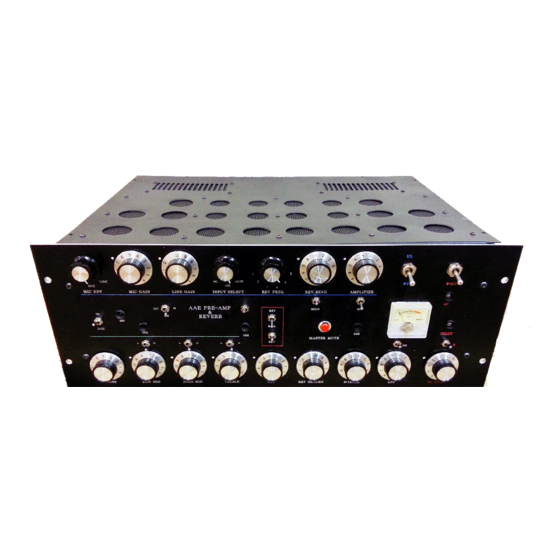
- Page 1 DU EQ 2022 DU EQ 2022 USER GUIDE STEREO...
-
Page 2: Table Of Contents
Page 1 of 25 Contents Contents ................................1 PLACEMENT ..............................4 THE MAIN UNIT ............................4 THE POWER SUPPLY UNIT ........................... 5 GROUND LIFT SWITCH ..........................5 PRECAUTIONS ............................. 6 OPERATING GUIDELINES CONTROLS & SWITCHES ..................7 (1) INPUT SECTION ............................7 (2) PASSIVE EQ SECTION .......................... - Page 3 Page 2 of 25...
- Page 4 Page 3 of 25...
-
Page 5: Placement
Page 4 of 25 PLACEMENT THE MAIN UNIT The location of the distortion unit (DU) is important. Its location/mounting must allow adequate air circulation from below, the sides and above it to disperse the heat that the tubes/semiconductors generate. Avoid hot locations such as near radiators or other heating units. IF THE UNIT IS MOUNTED ON A RACK: (a) If mounted on a rack ensure that the unit below it does not get hot. -
Page 6: The Power Supply Unit
Page 5 of 25 THE POWER SUPPLY UNIT (a) Before you connect the power supply to the mains, connect the two power supply cords to the power supply sockets. These are the two cables, one grey and one black, that come out from the back of the main unit. -
Page 7: Precautions
Page 6 of 25 PRECAUTIONS Please do not leave the unit switched on when not in use Each time: (a) you increase any gain settings (b) change from triode to pentode, (c) operate in OFF LOAD mode (d) operate in positive feedback (PFB) mode ... -
Page 8: Operating Guidelines Controls & Switches
Page 7 of 25 OPERATING GUIDELINES CONTROLS & SWITCHES DUAL MONO (a) The Tube amplifiers in this unit do not employ any form of negative feedback (NFB) in order to retain the harmonic sonic character of each tube and to be able to overdrive it to its full extent softly or harshly depending on how the controls/switches are set. -
Page 9: Passive Eq Section
Page 8 of 25 signal contains both even and odd products. Bass, drum-loops and keyboards/synths sound interesting in this mode. However, it also amplifies more. The SW1 (TRI/CASC) converts the input stage (as already explained) from a Triode to a cascode circuit with more distortion and gain. -
Page 10: Active Eq Section
Page 9 of 25 a) overdrive the input stage, before the EQ and use its controls to either boost or filter out harmonics that have been generated by the input stage, especially in cascode mode. Another option may be to: b) keep the input stage clean, (Triode Low distortion mode) and cut or boost certain frequencies of the signal that enters the following stages (SE &... -
Page 11: Main Differences Between Se & Pp Stages
Page 10 of 25 P8: HIGH MID BOOST control SW10: ON high mid frequency booster on/off or “KILL” switch There is a limiter before the input of both bass and high mid VFB's to avoid overloading them. Such type of overload must be avoided because it will result into instability and hard clipping. On high level signals, after a certain amplitude has been reached, this limiting action creates a form of compression and adds some sustain in the narrow range of the chosen frequencies. - Page 12 Page 11 of 25 Both SE and PP stages can function as clean audio amps with very little distortion only high enough to add colouration and “warmth”, if they are driven softly by adjusting their corresponding level controls and mode switches. They are both working in 'open loop' mode i.e. there is no Negative Feed Back (NFB) applied to them.
-
Page 13: Bias Control And How It Affects Distortion And Clipping In The Se Distortion Section
Page 12 of 25 BIAS CONTROL AND HOW IT AFFECTS DISTORTION AND CLIPPING IN THE SE DISTORTION SECTION The output stage of the SE section has a bias control that sets the amount of DC current that flows through the output tube and output inductor under idle (no signal) conditions. The lower this bias control is set the higher the even harmonic distortion generated by the SE output stage will be. -
Page 14: Differences Between Triode & Pentode
Page 13 of 25 P12: BIAS control it sets the amount of current that the SE output tube is operating on. SW13: SE-GAIN, L/H when this switch is set in H the gain inside the single ended stage is increased by 11.6 dBs. -
Page 15: The Push Pull (Pp) Output Stage
Page 14 of 25 For low SE DU distortion (just mild colouration) and low P8 settings, you can keep this switch in the up position because it introduces crossover distortion, unless of course you want to add this type of distortion to the mix. - Page 16 Page 15 of 25 Triode operation is preferred for clean sound like in the SE DU , whilst Pentone (PE 1) gives more distortion by operating the Screens of the output tubes at a lower voltage. Pentode operation in PE 2 is cleaner, with more headroom due to the higher Screen voltage.
-
Page 17: Preparation Before Switching On/Testing
Page 16 of 25 PREPARATION BEFORE SWITCHING ON/TESTING Connect the main unit to the power supply unit. (1) Ensure that the stand-by switch on the front panel of the of the main unit is OFF, i.e. the up position. This is because the high voltage (HT) must not be applied to the tubes until they warm up. FOR THE FIRST TEST (2) Turn these level controls fully anticlockwise: INPUT P1, BASS BOOST P5 , HIGH MID BOOST P8 , SE DRIVE P9, SE PFB P10, SE LEVEL P11 , PP DRIVE P13 and OUTPUT P14... - Page 18 Page 17 of 25 (8) Set EQ OUT /IN switch SW12 on IN. (9) For a flat response set Bass control P2 on half, Mid P3 just over half and Treble control P4 just below half. (10) Press tone control switches SW4/SW6/SW8 down i.e. ON. (11) Set TRI/CASC (triode/cascode) select switch SW1 on TRI (Triode).
-
Page 19: Switching On/Testing
Page 18 of 25 Due to the large number of controls and switches it is easy to get confused and not get identical signals in both channels if for instance one control/switch in one channel is in a slightly different setting in the other channel. - Page 20 Page 19 of 25 (1) Turn up P1 until Led OD1 lights up. (2) Turn the OUTPUT control P14 about half way and by turning up the PP Drive P13 you should be able to hear the audio signal. By pressing the EQ gain SW11 switch to the right (H), the signal increases by 8.6dB's.
- Page 21 Page 20 of 25 and then (b) re-adjust P14 to get the right level You can (i) overdrive the input in cascode mode by turning up P1, and keep the output clean by keeping P14 low, or (ii) set the input in triode mode, set P1 not too high and overdrive the output by turning up P14 and SW11 in H or (iii) try any combination of (i) and (ii).
-
Page 22: The Single Ended Distortion Stage (Se)
Page 21 of 25 (12) Testing the BASS BOOST and HIGH MID VFB's In order to get a better feel how the whole EQUALIZER system works, it is better to test the VFB's with the PP OUTPUT stage only, before inserting the SE DU in the mix. Also, for the first test set: (a)P15 on TRI, SW1 on TRI, and set P1 and P13 on relatively low settings to get a transparent sound, how low it depends on the signal strength of your sound source. - Page 23 Page 22 of 25 The channel that is disconnected is only the channel (top or bottom) where SW14 is located. This switch has no effect on the other SE channel or the other sections of the unit. When operating the TRI/PE1/PE2 P15 rotary switch you will still have to follow PROCEDURE (a,b,c,d,e) (a) Set the PP output stage so that it produces a neutral sound: P15 on TRI, set the SE LEVEL P11 control to maximum (10) in triode mode, but if you change into pentode modes in either SE, PP or both you may have to turn P11 down to keep the output level low OUTPUT P14 around half (you may have to...
- Page 24 Page 23 of 25 (j) At this stage you can experiment with using the SE section to overdrive the PP section in the various different modes (TRI, PE, etc) on both sections. When operating in OFF LOAD try to keep the BIAS control between 0 and 5, in most settings there is not much of a change between 5 and 10 in Off LOAD mode.
-
Page 25: Abbreviations
Page 24 of 25 (d) Turn up the PFB control P10 gradually and if oscillation starts turn it down until it stops. Remember that P10 and SE DRIVE control P9 are very interactive, and you may end up using them together. Make sure that you keep the output low through P11 and/or P14 (e) Repeat (d) in PENTODE mode, note that the output will increase, use P11 and/or P14 to reduce the output and you will have to re-adjust P9 and P10 too. - Page 26 Page 25 of 25 PFB= positive feedback NFB= negative feedback HT = High Tension, high voltage power supply line(s) (UK) B+ = abbreviation for HT in US ATT= attenuation...
Need help?
Do you have a question about the DU EQ 2022 and is the answer not in the manual?
Questions and answers