Advertisement
Quick Links
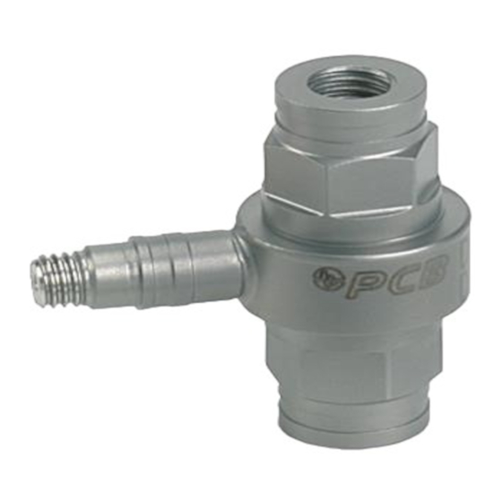
Model 221B03
Link ICP® quartz force sensor, 500 lb comp., 500 lb tension, 10 mV/lb
Installation and Operating Manual
For assistance with the operation of this product,
contact PCB Piezotronics, Inc.
Toll-free: 800-828-8840
24-hour SensorLine: 716-684-0001
Fax: 716-684-0987
E-mail: info@pcb.com
Web: www.pcb.com
Advertisement

Related Manuals for PCB Piezotronics 221B03


Summary of Contents for PCB Piezotronics 221B03
- Page 1 Model 221B03 Link ICP® quartz force sensor, 500 lb comp., 500 lb tension, 10 mV/lb Installation and Operating Manual For assistance with the operation of this product, contact PCB Piezotronics, Inc. Toll-free: 800-828-8840 24-hour SensorLine: 716-684-0001 Fax: 716-684-0987 E-mail: info@pcb.com...
-
Page 2: Repair And Maintenance
Assistance is needed to safely operate equipment PCB Piezotronics is an ISO-9001 certified company whose Damage is visible or suspected calibration services are accredited by A2LA to ISO/IEC Equipment fails or malfunctions 17025, with full traceability to SI through N.I.S.T. - Page 3 CAUTION Refers to hazards that could damage the instrument. NOTE Indicates tips, recommendations and important information. The notes simplify processes and contain additional information on particular operating steps. The following symbols may be found on the equipment described in this manual: This symbol on the unit indicates that high voltage may be present.
- Page 4 PCB工业监视和测量设备 - 中国RoHS2公布表 PCB Industrial Monitoring and Measuring Equipment - China RoHS 2 Disclosure Table 有害物质 镉 汞 铅 (Pb) 六价铬 (Cr(VI)) 多溴联苯 (PBB) 多溴二苯醚 (PBDE) 部件名称 (Hg) (Cd) 住房 PCB板 电气连接器 压电晶体 环氧 铁氟龙 电子 厚膜基板 电线 电缆 塑料 焊接...
- Page 5 Component Name Hazardous Substances Lead (Pb) Mercury (Hg) Cadmium (Cd) Chromium VI Polybrominated Polybrominated Compounds Biphenyls (PBB) Diphenyl Ethers (Cr(VI)) (PBDE) Housing PCB Board Electrical Connectors Piezoelectric Crystals Epoxy Teflon Electronics Thick Film Substrate Wires Cables Plastic Solder Copper Alloy/Brass This table is prepared in accordance with the provisions of SJ/T 11364.
- Page 6 FORCE SENSOR OPERATION MANUAL 1.0 INTRODUCTION operate through standard, low-cost coaxial cable, and do not require expensive charge amplifiers. ICP force sensors incorporate a built-in MOSFET Refer to the installation/outline drawing and specification sheet microelectronic amplifier. This serves to convert the high at the back of this manual for details and dimensions of the impedance charge output into a low impedance voltage signal particular sensor model number(s) purchased.
- Page 7 FORCE SENSOR OPERATION MANUAL Figure 3 - Series 200 ICP Impact Sensor Polyimide film tape covers the cap surface to reduce high frequency ringing associated with metal-to-metal impacts. Internal mounting holes with uniform 10-32 threads are prepared on each end of the sensor in the smaller models. Two Model 081B05-mounting studs (M081B05 for metric Ring Force Sensor Figure 4 - Series 201 to 207 ICP...
- Page 8 FORCE SENSOR OPERATION MANUAL Figure 6 outlines some possible mounting configurations of the link series of sensors. Figure 6 – Series 221 to 227 ICP ® Force Link Sensor Mounting Method 3- COMPONENT TRIAX SENSORS PCB’s line of 3-Component force sensors is capable of simultaneously measuring force in three (3) orthogonal directions (X, Y, and Z).
- Page 9 FORCE SENSOR OPERATION MANUAL repair document for proper instructions for returning the sensor to PCB for recalibration. Figure 8 – SERIES 3-COMPONENT TRIAX FORCE SENSORS version Charge mode version ® PENETRATION Penetration style sensors are similar to the axial models but are specifically designed for compression and impact force measurements in materials testing applications.
-
Page 10: Installation
FORCE SENSOR OPERATION MANUAL the sensor. Link, integrated link, and freestanding installations sensor sensitivity and result in erroneous data (see Figure 11). are possible as outlined in Figure 9. A good mating surface may be obtained by lapping, turning, spot-facing, or surface grinding. - Page 11 FORCE SENSOR OPERATION MANUAL Figure 12 - Cable Strain Relief A non-typical installation is shown on the right side of Figure 13. In this installation, the stud or bolt used to apply the preload does not shunt part of the applied force. The plate on top of the sensor has a clearance hole that the stud or bolt passes through.
- Page 12 FORCE SENSOR OPERATION MANUAL traceable reference sensor. Generally, a preload of 20% (full Step Force Ring Preload Incremental Sensitivity scale operating range of the force ring) is applied before Increment (lbf) (mV/lbf) Models Steps recording of measurement data. Allow the static component of (mV) the signal to discharge before calibration.
- Page 13 FORCE SENSOR OPERATION MANUAL 5.0 OPERATION the cable as this will fatigue the electrical center pin resulting in an intermittent connector or damaged cable. APPLICATION OF A FORCE For best results, the applied force should be distributed evenly over the contact surface of the sensor. Care should be taken to limit the bending moment induced into the sensor by edge loading or off-axis loading of the sensor.
- Page 14 FORCE SENSOR OPERATION MANUAL 7.0 LOW-FREQUENCY MONITORING illustrated in Figure 16, this is an exponential decay. Approximately five DTC intervals are needed for a peak signal Force sensors used for applications in short term, steady state to naturally decay back to zero. monitoring, such as sensor calibration, or short term, quasi- static testing should be powered by signal conditioners that The rule of thumb for signal discharge, as outlined in Figure...
-
Page 15: Troubleshooting
Output voltage moves from YELLOW to GREEN slowly until ICP is a registered trademark of PCB Piezotronics charging is complete. AC coupled signal conditioners require sufficient time to charge the internal coupling capacitor. Allow signal conditioner to charge for five (5) discharge time constants for stable operation. - Page 16 Model Number Revision: K ICP® FORCE SENSOR 221B03 ECN #: 45758 Performance ENGLISH OPTIONAL VERSIONS Sensitivity(± 15 %) 10 mV/lb 2248.2 mV/kN Optional versions have identical specifications and accessories as listed for the standard model Measurement Range(Compression) 500 lb 2.224 kN except where noted below.
Need help?
Do you have a question about the 221B03 and is the answer not in the manual?
Questions and answers