Table of Contents
Advertisement
Quick Links
Advertisement
Table of Contents

Summary of Contents for Schleuniger ACO 08
- Page 1 ACO 08 Crimp Force Monitor Operating manual Edition 1.00 (08-2020)
- Page 2 P +86 21 62 52 66 77 P +41 41 754 53 53 F +86 21 62 40 86 55 F +41 41 754 53 50 sales@schleuniger.com.cn solutions@schleuniger.ch www.schleuniger.cn www.schleuniger.ch 2 | 52 Operating Manual | Edition 1.00 (08-2020) | ACO 08...
-
Page 3: Table Of Contents
TABLE OF CONTENTS General ............................6 1.1 Dealer ................................... 6 1.2 Year of manufacture / device type ......................6 1.3 Information about the operating manual ....................6 1.3.1 Content of the manual ........................6 1.3.2 Storage location ..........................7 1.3.3 Responsibilities ..........................7 1.4 General symbols and keys .......................... - Page 4 6.1.1 Remove the ACO 08 and the accessories from the packaging........21 6.1.2 Place the device at its final location ..................21 6.1.3 Install the crimping machine-specific cable kit and connect it with the ACO 08 ..21 6.2 Commissioning .............................. 21 General Handling / Operation ....................
- Page 5 11.1 Spare parts ............................... 45 12 Exploded Drawings ........................ 46 13 Block Diagram ........................47 14 PLC Interface ........................... 48 15 Notes ............................50 16 Index ............................51 Operating Manual | Edition 1.00 (08-2020) | ACO 08 5 | 52...
-
Page 6: General
GENERAL Thank you for choosing Schleuniger technology. You have purchased a high-performance Schleuniger product that has been developed with care and manufactured in cooperation with our partner, KMF Messtechnik. Carefully read this operating manual. It contains important tips and safety instructions to ensure efficient, precise and reliable production of cables. -
Page 7: Storage Location
Text reference to elements in a sample. preceding figure. Content reference (topic): Disposal: Important safety-related content Waste material that must be recycled reference. and not disposed of in domestic waste. Operating Manual | Edition 1.00 (08-2020) | ACO 08 7 | 52... -
Page 8: Key
This operating manual must be treated confidentially. It is only intended for persons who are involved in work with the product. The operating manual must not be made available to third parties without the express written consent of the manufacturer. 8 | 52 Operating Manual | Edition 1.00 (08-2020) | ACO 08... -
Page 9: Privacy Protection
Incorrect or faulty spare parts can lead to damage, malfunction or total failure of the product as well as affecting the safety of the operating personnel. Therefore, use Schleuniger only original spare parts from Operating Manual | Edition 1.00 (08-2020) | ACO 08 9 | 52... -
Page 10: Safety
Schleuniger Only use original accessories, especially interface cables (electromagnetic ■ compatibility). SOURCES OF DANGER / RESIDUAL DANGERS There are hazards involved when using technical products. 10 | 52 Operating Manual | Edition 1.00 (08-2020) | ACO 08... -
Page 11: Proper And Intended Use
The product has been designed and built exclusively for the intended use specified below: The ACO 08 is used for monitoring and analyzing the crimping process within the range according to the technical data. Nonadherence can lead to injury to the operating personnel and material damage. -
Page 12: Modification And Conversion To The Product
This also includes knowledge of accident prevention regulations and first aid. 2.7.1.5 Third parties External personnel solicited the operating company, service technicians and employees from Schleuniger 12 | 52 Operating Manual | Edition 1.00 (08-2020) | ACO 08... -
Page 13: Personal Protective Equipment
Defective safety equipment must be repaired immediately. Only then can the product be put back into operation. Never operate the product with the safety cover open. ■ Operating Manual | Edition 1.00 (08-2020) | ACO 08 13 | 52... -
Page 14: Transport / Packaging / Storage
Handling the packaging materials Recycle any packaging no longer needed. 10 Disposal See chapter SHIPPING Use the associated packaging before shipping the device. Disconnect all connected cables from the device. 14 | 52 Operating Manual | Edition 1.00 (08-2020) | ACO 08... -
Page 15: Product Specifications
IP 20 Limit values, incl. measuring range 0 – 20000 Units N, lb, without Channels Data capacity 8 GB (µSD) Sensor type Piezo and DMS Interfaces Ethernet, USB, Operating Manual | Edition 1.00 (08-2020) | ACO 08 15 | 52... -
Page 16: Setup Location
The rating plate is located on the side wall and contains the following specifications. 1 Product 4 Permissible operating voltages 2 Serial number 5 Internal fuses 3 Year of manufacture 6 Manufacturer 16 | 52 Operating Manual | Edition 1.00 (08-2020) | ACO 08... -
Page 17: Product Description
CONCEPT The ACO 08 crimp force monitoring monitors and analyzes the crimping process. The device can be used to evaluate and optimize the crimping processes in the sector of further development of crimping technology, as well as for monitoring, control, and checking the production process. -
Page 18: Front View
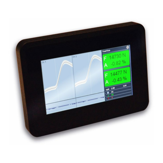
Product description FRONT VIEW Fig. 2: Control elements 1 Touch display with graphical user Interface 18 | 52 Operating Manual | Edition 1.00 (08-2020) | ACO 08... -
Page 19: Rear View
4 Mains socket for external mains supply CONTROL ELEMENTS AND INTERFACES Touch display The ACO 08 does not have any physical switches. All inputs are made via gestures or digital buttons on the graphical user interface. Sensor cable connections (channels 1 and 2) Input sockets for the signal of the force sensors. -
Page 20: Scope Of Delivery
Product description USB Interface Enables service functions such as firmware updates or reading data Digital IO interface Enables the output and receipt of control signals between ACO 08 and crimping machine SCOPE OF DELIVERY See goods data sheet. ACCESSORIES Please use only original manufacturer accessories. -
Page 21: Installation
6.1.2 Place the device at its final location. 6.1.3 Install the crimping machine-specific cable kit and connect it with the ACO 08. COMMISSIONING Following the proper installation, the levels of the digital IOs must be adapted to the crimping machine. Common crimping machines are listed in the “Machine profile” menu and can be simply selected. -
Page 22: General Handling / Operation
The internal process instructions must be followed in the machining process. ■ USER INTERFACE The ACO 08 does not have any physical pushbuttons or switches. It is only operated via the graphic user interface. The following principal inputs can be made: Selection by tapping tiles or buttons ■... -
Page 23: Monitoring Mode
To access the monitoring mode, select the “monitoring mode” tile in the main menu. Operating Manual | Edition 1.00 (08-2020) | ACO 08 23 | 52... - Page 24 Select a channel in the 2-channel presentation by tapping the corresponding graphic image. Curve and envelope of the channel are displayed enlarged. Tap the graphic image to return to the 2-channel display. 24 | 52 Operating Manual | Edition 1.00 (08-2020) | ACO 08...
- Page 25 If configured in the setup, the error must be acknowledged on user level 1 by entering the password. Acknowledgment without password is possible on user level 2 or 3. Operating Manual | Edition 1.00 (08-2020) | ACO 08 25 | 52...
-
Page 26: Teaching
If a curve deviates too much from the previous curves, the message “invalid Ref” appears automatically. Select “OK” to generate the last curve again or “discard” to start over with teaching. 26 | 52 Operating Manual | Edition 1.00 (08-2020) | ACO 08... -
Page 27: Setup
ACO 08 switches to monitoring mode. 7.2.4 Setup In setup all setting parameters concerning the ACO 08 can be set. At least user level 2 is required to access setup. To access the setup mode, select the “setup”... - Page 28 Max drift Limit value of drift compensation. An error is 1-100 % signaled if this value is exceeded. Gain Boosting of the sensor signal 1/2/4/8/16/32 x 28 | 52 Operating Manual | Edition 1.00 (08-2020) | ACO 08...
- Page 29 Secure: Acknowledgment by password entry Auto reference check Evaluates the deviation of curves automatically on/off in reference mode. Each reference must be confirmed manually if disabled. Operating Manual | Edition 1.00 (08-2020) | ACO 08 29 | 52...
- Page 30 Password for user level 3 String Language Language of the user interface DE/EN Ref permission Permit to form reference curve for user level 1 on/off Unit Unit of the measuring results N/lb/none 30 | 52 Operating Manual | Edition 1.00 (08-2020) | ACO 08...
-
Page 31: User Levels
General handling / operation 7.2.5 User levels The ACO 08 is controlled via 3 user levels where each of them has different access rights. To access the user level selection, select the “user selection” tile in the main menu. Fig. 8: User selection... - Page 32 Use only user level 1 in default operation! Make sure to switch again to user level 1 after you have made corresponding settings on a higher user level. 32 | 52 Operating Manual | Edition 1.00 (08-2020) | ACO 08...
-
Page 33: Job Management
7.2.6 Job management The ACO 08 provides the option of working with jobs. Settings, parameters and measuring results are stored in a job. To access job management, select the “job management” tile on the main menu (requires user level 2 or 3). - Page 34 If you do not yet want to generate a reference curve at this time, swipe from the right edge of the display onto the display. The ACO 08 switches to the main menu. 34 | 52 Operating Manual | Edition 1.00 (08-2020) | ACO 08...
- Page 35 Clear job Highlight an existing job and choose “clear”. Answer the verification prompt with “Yes”. All measuring results within the selected job are cleared. Operating Manual | Edition 1.00 (08-2020) | ACO 08 35 | 52...
-
Page 36: Information Dialog
The job “Basic Job” cannot be deleted. 7.2.7 Information dialog Information on the device is provided here. To access the information dialog, select the “info” tile in the main menu. 36 | 52 Operating Manual | Edition 1.00 (08-2020) | ACO 08... -
Page 37: Automatic Parametrization
To access automatic parametrization, swipe in the main menu from the right across the right edge of the display (requires user level 2 or 3). Select the tile “automatic parametrization”. Operating Manual | Edition 1.00 (08-2020) | ACO 08 37 | 52... -
Page 38: Headroom Test
To access the headroom test, swipe in the main menu from the right across the right edge of the display (requires user level 2 or 3). Select the “Headroom test” tile. 38 | 52 Operating Manual | Edition 1.00 (08-2020) | ACO 08... - Page 39 Carry out the corresponding number of empty crimping operations, i.e. crimp empty terminal sleeves without conductor. The results will be displayed. Operating Manual | Edition 1.00 (08-2020) | ACO 08 39 | 52...
-
Page 40: Machine Profiles
(requires user level 2 or 3). Select the “Machine profile” tile. Mark the desired machine and confirm with “select”. 40 | 52 Operating Manual | Edition 1.00 (08-2020) | ACO 08... -
Page 41: Diagnosis / Troubleshooting
Check or clean the tool/base Force bypass plate area Measurement is carried out, no External trigger force signal Force sensor not connected / Check force sensor connection, defective replace force sensor Operating Manual | Edition 1.00 (08-2020) | ACO 08 41 | 52... - Page 42 Check connecting cable/power supply, replace if necessary Device signal error with each Tolerances no longer current; Check tool/machine for measurement wrong references changes or contamination; generate new references 42 | 52 Operating Manual | Edition 1.00 (08-2020) | ACO 08...
-
Page 43: Maintenance
Device switched off and disconnected from power supply system Notice Cleaning! Do not use aggressive solvents for cleaning. ■ Display and plastic parts will be damaged. Clean housing and display with a damp cloth. Operating Manual | Edition 1.00 (08-2020) | ACO 08 43 | 52... -
Page 44: Disposal
Schleuniger products mainly consist of the following materials: Material Disposal Aluminum Metal waste Steel Metal waste Other metals Metal waste Electronic materials Electronic waste Plastic Recycling 44 | 52 Operating Manual | Edition 1.00 (08-2020) | ACO 08... -
Page 45: Parts Catalog
Ball joint incl. flange for ACO08 10100100 Connecting rod machine to ACO08 (M12 / M4) 10100009 Sensor with 1.1 m cable and BNC plug 10100018 Start/Stop Kit ACO07 SC/UC 200 Operating Manual | Edition 1.00 (08-2020) | ACO 08 45 | 52... -
Page 46: Exploded Drawings
Exploded drawings EXPLODED DRAWINGS 46 | 52 Operating Manual | Edition 1.00 (08-2020) | ACO 08... -
Page 47: Block Diagram
Block diagram BLOCK DIAGRAM Operating Manual | Edition 1.00 (08-2020) | ACO 08 47 | 52... -
Page 48: Plc Interface
PLC Interface PLC INTERFACE 48 | 52 Operating Manual | Edition 1.00 (08-2020) | ACO 08... - Page 49 PLC Interface Operating Manual | Edition 1.00 (08-2020) | ACO 08 49 | 52...
-
Page 50: Notes
Notes NOTES 50 | 52 Operating Manual | Edition 1.00 (08-2020) | ACO 08... -
Page 51: Index
Safety equipment 14 Safety symbols used 12 General safety advice 10 Symbols 7 Key 8 Transportation 15 Limitation of liability 8 Warnings 10 Warranty conditions 9 Personal protective equipment 13 Operating Manual | Edition 1.00 (08-2020) | ACO 08 51 | 52... - Page 52 Index 52 | 52 Operating Manual | Edition 1.00 (08-2020) | ACO 08...
Need help?
Do you have a question about the ACO 08 and is the answer not in the manual?
Questions and answers