Table of Contents
Advertisement
Quick Links
Advertisement
Table of Contents

Subscribe to Our Youtube Channel
Summary of Contents for Rickard DU1011-1
- Page 1 User Manual for the Zone Controller...
-
Page 2: Table Of Contents
Local User Interface ....................34 4.1.1.1.7 Email ........................... 34 4.1.1.1.8 Upload (to cloud server) ....................35 4.1.1.1.9 Security ........................36 4.1.1.1.10 Settings Backup and Restore ................... 37 4.1.1.1.11 Software Update ....................... 38 4.1.1.2 Menu item: Control ......................38 4.1.1.2.1 Global .......................... 39 RICKARD 2021... - Page 3 5.1.2.4 Step 4 – Configure the Network settings ................76 5.1.2.5 Step 5 – Configure BACnet ....................76 5.1.2.6 Step 6 – Configure Local User Interface ................76 5.1.2.7 Step 7 – Configure the Diffuser and Partition network ............77 RICKARD 2021...
- Page 4 Appendix A: Available list of data points (at date of issue) ................83 Appendix B: Zone Controller Points List (Template) ................... 84 Appendix C: PICS Statement for the Zone Controller ................. 85 Appendix D: Zone Controller Calculations....................88 RICKARD 2021...
- Page 5 Figure 45: Hardware IO display ........................57 Figure 46: Points List display ........................58 Figure 47: ZC Browser list ........................... 59 Figure 48: Diffuser Summary ........................60 Figure 49: ZC Event Log ..........................61 Figure 50: Trend log display (example) ....................... 62 RICKARD 2021...
- Page 6 Table 11: Digital Inputs ..........................82 Table 12: Digital Outputs ..........................82 Table 13: Analog Outputs ..........................82 Table 14: Analog Inputs ..........................82 Table 15: Communications .......................... 82 Table 16: Protocol Compliance ........................82 Table 17: Power Requirements ........................82 RICKARD 2021...
- Page 7 Pressure Control Damper Proportional Integral PICS Protocol Implementation Conformance Standard Proportional Integral Derivative Power Supply Unit Relative Humidity Remote User Interface System on Module Universal Serial Bus Variable Refrigerant Flow Variable Air Volume Variable Speed Drive Zone Controller RICKARD 2021...
-
Page 8: Introduction
The ZC typically interfaces to the following items via an Ethernet connection: Building Management System (BMS) • Multiples of up to 60 diffusers per Master Communication Unit (MCU) using the BACnet protocol • • Other Zone Controllers • Remote Client Workstation with a Web Browser Modbus TCP unit • RICKARD 2021... -
Page 9: Figure 2: Zone Controller Application Diagram
AHU electrical wiring diagram. The installation is then configured by using the Remote User Interface (RUI). The typical Air Handling Unit that is controlled by the Zone Controller is depicted in Figure 3. The sensors / actuators relevant to the different areas of the AHU are listed below. RICKARD 2021... -
Page 10: Figure 3: Zone Controller Depiction Of Air Handling Unit
The sensors / actuators that may form part of this area are: a) Supply Air Temperature sensor b) Supply Air Pressure sensor c) Supply Air (bypass) damper d) Filter dirty switch or Differential pressure switch e) Supply Air fan Heating / Cooling coil(s) g) Electric heating h) Humidifier RICKARD 2021... -
Page 11: Document Overview
This document is structured as follows: Chapter 1 – Introduction Chapter 2 – Communication Chapter 3 – Installation Chapter 4 – User Interfaces Chapter 5 – System Operation Chapter 6 – Technical Specifications The suggested minimum reading is: RICKARD 2021... -
Page 12: Functional Overview / Main Features
A minimum or maximum pressure setpoint is used by the fan PI loop control. Diffuser Average Disk to fan speed (no PI loop) - The diffuser average disk position is directly converted to a linear fan setpoint between a minimum and maximum fan speed value. RICKARD 2021... -
Page 13: Configuration
The definition of the points list must be aligned with the physical installation for proper operation of the Zone Controller. 1.3.4 Log files A log file is maintained which captures all major events of the system operation, including the time of occurrence. RICKARD 2021... -
Page 14: Trend Logs
Micro SD Card for expandable memory up to 64GB. • 1 x 100Mbit switch ports (Ethernet 0). • RS485 port for Modbus. • • RS485 port for ms/tp (future release). • Dual-band 2.4/5 GHz and 802.11 ac/a/b/g/n (optional). RICKARD 2021... -
Page 15: General Specifications
All inputs and outputs (except for relay outputs and communication ports) are over-voltage protected up to 24 VAC and short-circuit protected. Environmental Operating temperature 0⁰C to +50⁰C. Storage temperature -10⁰C to 60⁰C. Relative humidity 10-95%, non-condensing. Weight 0.5 kg Dimensions 230 mm x 150 mm x 50 mm RICKARD 2021... -
Page 16: Led Indicators
EN 55024 EN 61000-4-4 Fast Transient Burst 1 kV clamp & 2 kV direct EN 55024 EN 61000-4-6 Conducted Immunity 10 V (rms) EN 55022 CISPR 32 Radiated Emissions Class A EN 55022 CISPR 32 Conducted Emissions Class B RICKARD 2021... -
Page 17: Communication
BACnet protocol. The MCU2 implements a BACnet server whereas the ZC implements a BACnet client. 2.1.3 RS485 This interface allows for both Modbus and ms/tp interfacing. The Modbus implementation allows for TCP and serial interfaces (RTU or ASCII). The ms/tp interface is for future release. RICKARD 2021... -
Page 18: Installation
Exposure to aggressive and polluting atmospheres (e.g. sulphur and ammonia vapours, salt mist, fumes) that can cause corrosion and/or oxidation; Excessive exposure to dust; • Exposure to water and condensate; • Electrically noisy environment without the necessary precautions (e.g. cabling routed in close • proximity to VSD equipment) RICKARD 2021... -
Page 19: Mounting
ZONE CONTROLLER USER MANUAL 3.3 Mounting The ZC is mounted on a wall or a recessed wall box using the din rail brackets at the back of the ZC cover, refer Figure 5. Figure 5: ZC din rail mounting brackets RICKARD 2021... -
Page 20: Power Supply
100-BASE-TX segments must use Category 5 cable. Category 5e cable is highly recommended as the minimum for new installations. 4) The Ethernet port employs Auto-MDIX technology so that either straight-through or crossover cables can be used to connect to the network. RICKARD 2021... -
Page 21: Input / Output Connections
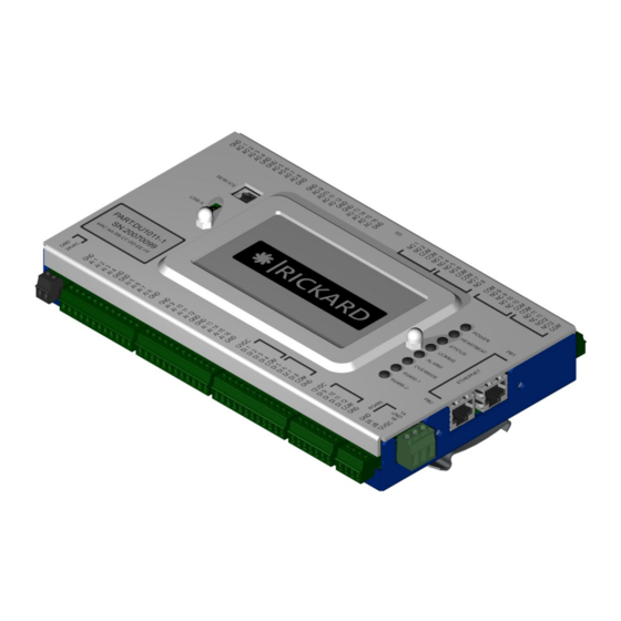
ZONE CONTROLLER USER MANUAL 3.6 Input / Output connections Refer Figure 6 for a layout of the ZC PCB with terminals. The characteristics of the digital and analog inputs and outputs are described below. Figure 6: ZC physical layout RICKARD 2021... -
Page 22: Digital Input (Ac Or Dc)
PIN 5 DI 4 DI 12 PIN 6 COM 1-4 COM 9-12 PIN 7 DI 5 PIN 8 DI 6 PIN 9 DI 7 PIN 10 DI 8 PIN 11 COM 5-8 PIN 12 Figure 7: Digital Input connections RICKARD 2021... -
Page 23: Digital Output
NO 5 COM 11 PIN 5 NO 6 NO 11 PIN 4 COM 5-8 NC 11 PIN 3 COM 5-8 NO 12 PIN 2 NO 7 NC 12 PIN 1 NO 8 COM 12 Figure 8: Digital Output connections RICKARD 2021... -
Page 24: Analog Input
AI 4 AI 12 PIN 6 PIN 7 PIN 8 AI 5 AI 13 PIN 9 AI 6 AI 14 PIN 10 AI 7 AI 15 PIN 11 AI 8 AI 16 PIN 12 Figure 10: Analog Input connections RICKARD 2021... -
Page 25: Analog Output
Refer to Table 8 for the relevant points list table. The list of available I/O data points is given in Appendix A. A template for a points list is given in Appendix B for use in new installations. RICKARD 2021... -
Page 26: Figure 12: Example Zone Controller To Ahu Wiring Diagram (See Table 8)
ZONE CONTROLLER USER MANUAL Figure 12: Example Zone Controller to AHU Wiring diagram (see Table 8) Figure 12: Example Zone Controller to AHU Wiring diagram (see Table 8) RICKARD 2021... -
Page 27: Table 8: Example Points List (See Figure 11)
Binary Sensor HW no Notify ReadOnly Digital DI/Supply/FanTrip Binary Sensor HW no Notify ReadOnly Digital DO/Panel/ChillerCoolingEnable Binary Actuator HW no None ReadWrite Digital DO/Supply/FanEnable Binary Actuator HW no None ReadWrite Digital DO/Exhaust/FanEnable Binary Actuator HW no None ReadWrite Digital RICKARD 2021... -
Page 28: User Interfaces
Items 1 to 5 are visible on the dashboard and are described below. • Menu Item Item • Mode and Control Item 3 • Setpoint and Diffuser data Item 4 • ZC Status information Item 5 • ZC Notification icons RICKARD 2021... -
Page 29: Menu (Item 1)
Select <System> from the main menu in the web browser Select the <Device> menu item to set the device data. Refer Figure 14 for a depiction of the Device settings page. Select the <Update> button. Figure 14: Device display 4.1.1.1.2 Time and Date RICKARD 2021... -
Page 30: Figure 15: Set Time, Date And Time Zone
Select the <Time and Date> menu item to set the current date, time and time zone. b) Refer Figure 15 for a depiction of the Time and Date settings page. c) Note that internet time and date takes precedence. d) Select the <Update> button. Figure 15: Set Time, Date and Time zone RICKARD 2021... -
Page 31: Network
Select whether to use DHCP (Obtain IP and DNS automatically) • If DHCP is not selected, provide the following for a static IP address setting: o IP Address o Subnet Mask o Default Gateway o DNS Server Address(es) c) Select the <Update> button. Figure 16: Network Settings RICKARD 2021... -
Page 32: Bacnet
For a TCP port, the Interface Selection can be set to one of the following: • Disabled, refer Figure 21. TCP/IP, refer Figure 22. IP e.g. 127.0.0.1 Port e.g. 502 d) Select the <Update> button. RICKARD 2021... -
Page 33: Figure 18: Serial Modbus Display
ZONE CONTROLLER USER MANUAL Figure 18: Serial Modbus display Figure 19: Serial Modbus display for RTU Interface Selection Figure 20: Serial Modbus display for ASCII Interface Selection RICKARD 2021... -
Page 34: Local User Interface
Pin Code: Enter a pin code (minimum of 3, maximum of 8 digits) Automatic logout time: Enter the time in seconds of inactivity before the LUI is locked. • d) Select the <Update> button. Figure 23: LUI Settings 4.1.1.1.7 Email RICKARD 2021... -
Page 35: Upload (To Cloud Server)
If the user has not registered as a user on the cloud server, he/she can do that but need a valid ZC Security Code. A valid ZC Security Code can be obtained from the <Security> menu. RICKARD 2021... -
Page 36: Security
• If required, generate a ZC Security Code for cloud server access. • If required, change the password of the current account. Figure 26: Security display RICKARD 2021... -
Page 37: Settings Backup And Restore
Restore – Upload a settings file to the ZC • The Configuration data can be saved and restored by selecting the <Control> menu from the main menu in the web browser and then <Config Backup>, refer 4.1.1.2.11. Figure 27: Settings Backup display RICKARD 2021... -
Page 38: Software Update
A summary of the setup process is given below. Contact Local Support for detail assistance. From the Dashboard, select the <Control> menu. From the <Control> menu, one of the following submenus can be selected: • <Global> - configure the Control options, refer 4.1.1.2.1 RICKARD 2021... -
Page 39: Global
When the time to start control has been reached, one of the following conditions may be used by the ZC to transfer from Purge to Control (depending on the active functions selected in a)): • The pressure input value has reached the pressure setpoint; RICKARD 2021... -
Page 40: Temperature
(rundown) at the end after stopping temperature control. 4.1.1.2.2 Temperature In the <Control> menu, select the <Temperature> submenu to configure the Temperature Control. Refer Figure 31 for a typical Temperature Control Configuration display. RICKARD 2021... -
Page 41: Figure 31: Temperature Control Configuration
ZONE CONTROLLER USER MANUAL Figure 31: Temperature Control Configuration Select Cooling / Heating Hardware RICKARD 2021... - Page 42 Some DX units require a minimum duration for Heating or Cooling to be active. iii) Minimum Fan Only Duration If the ZC transfers from Heating/Cooling to FanOnly, this parameter will specify the • delay in minutes that the ZC will remain in FanOnly i.e. not Heating or Cooling Modes. RICKARD 2021...
- Page 43 Refer Appendix D-1 for an overview of the implemented generic PI loop. For the Temperature PI loop the following parameters may be configured: • Output Value when disabled • Output Minimum • Output Maximum • Delta (maximum abs(error)) dead-band • Gain [K value] • Reset rate [repeats per minute] RICKARD 2021...
-
Page 44: Pressure
Gain [K value] • • Reset rate [repeats per minute] Pressure reset control, same as in a) above, but with two setpoints based on average disk position. If the pressure reset control is selected, the following parameters must be provided: RICKARD 2021... - Page 45 Disk position high % (This average disk position will result in the supply air maximum fan speed) Fan speed low % (Fan speed when diffuser disk position at low) • Fan speed high % (Fan speed when diffuser disk position at high) • speed (required fan speed at input disk position Disk position RICKARD 2021...
-
Page 46: Damper & Fan
Bypass Section: Define the dampers present in this area: None / Damper Return Air Section: Define the dampers present in this area: None / Damper : Define the Minimum Damper Position to use if the Minimum Damper Position Economy mode or CO2 is disabled. RICKARD 2021... -
Page 47: Humidity
Refer Appendix D-1 for an overview of the implemented generic PI loop. For the Humidity PI loop the following parameters may be configured: • Output Value when disabled • Output Minimum • Output Maximum • Delta (maximum abs(error)) dead-band • Gain [K value] • Reset rate [repeats per minute] RICKARD 2021... -
Page 48: Economy & Co2
Refer Appendix D-1 for an overview of the implemented generic PI loop. For the CO2 PI loop the following parameters may be configured: • Output Value when disabled • Output Minimum • Output Maximum • Delta (maximum abs(error)) dead-band • Gain [K value] RICKARD 2021... -
Page 49: Data Points
Data Points on the GUI. Figure 36: Show All Data Points Button (hiding) Figure 37: Unused Data Points hidden Figure 38: Show All Data Points button Figure 39: Unused Data Points shown (showing) RICKARD 2021... -
Page 50: Table 9: Summary Of Data Point Configuration Parameters
BACnet Point Actuators Binary BACnet Point Sensors Binary BACnet Point Actuators Analog Modbus Point Sensors Analog Modbus Point Actuators Binary Modbus Point Sensors Binary Modbus Point Actuators Software Enumerations Software Numeric Software Binary Hardware numbers BACnet points Modbus points RICKARD 2021... -
Page 51: Simulate
The following parameters must be provided: • Digital input/output datapoint name (e.g. DI/Return/FanTrip) Enabled flag (when set the specific digital input will be simulated) • Active (i.e. Enable/Disable or True/False or Yes/No) • Duration of the test (hh:mm:ss) • 4.1.1.2.9 Diffuser & Partition RICKARD 2021... -
Page 52: Figure 40: Diffuser Options
Under the <Partitions> tab, the following may be configured: The following parameters may be configured, refer Figure 41: • Partition name Partition schedule. Note that the partition schedule must be set-up in conjunction with the • overall control schedule, refer 4.1.1.2.10. The following verification is done: RICKARD 2021... -
Page 53: Figure 41: Partition Schedule
MCU list to display the MCU setup page In the list of diffusers, the user may select the diffusers to use. The user has “Use all” and • “Use none” buttons to support the selection RICKARD 2021... -
Page 54: Figure 42: Mcu And Diffuser List
Under the <Partition IO Dampers> tab, the user may select the IO Damper for the corresponding partition. • One or more damper may be assigned to a specific partition and the datapoint may then be configured by clicking on “Edit DataPoint”. RICKARD 2021... -
Page 55: Schedule
15 minutes and start at 06:45. As soon as the ‘purging complete’ event is set at or after 07:00, the ZC will operate with the control parameters selected. The ZC will stop controlling every day at 18:00 and then go through a rundown period of 30 minutes to stop at 18:30. RICKARD 2021... -
Page 56: Configuration Backup And Restore
Eject USB: Eject the USB The Settings data can be saved and restored by selecting the <System> menu from the main menu in the web browser and then <Settings Backup>, refer 4.1.1.1.10. Figure 44: Config Backup display RICKARD 2021... -
Page 57: Menu Item: Io
NOT IN USE: The point is not required for the operation of the current configuration and was also not enabled by the user; point is ignored and will never be set/receive updates. o NVI NOT VISIBLE: The point has been set as Not Visible by the user; the point RICKARD 2021... -
Page 58: Figure 46: Points List Display
It can assist in troubleshooting when the present value is different from the read value. The value will be displayed in different colours to indicate: Value is simulated – green Value is in override - purple Figure 46: Points List display RICKARD 2021... -
Page 59: Menu Item: Dashboard
This menu item provides a list of all the ZC’s visible on the BACnet network. Navigation to another ZC can be done by highlighting and clicking the relevant line in the list. Refer Figure 47 for an example of a list. Figure 47: ZC Browser list RICKARD 2021... -
Page 60: Diffuser Summary
ZONE CONTROLLER USER MANUAL 4.1.1.4.2 Diffuser Summary A summary of the configured diffusers is displayed, refer Figure 48. Figure 48: Diffuser Summary RICKARD 2021... -
Page 61: Menu Item: Logs
The user can perform the following actions on the Event Log: • Filter the display to a subset by typing in a keyword Clear the Event Log • Refresh the Event Log • Refer Figure 49 for an example of an Event Log. Figure 49: ZC Event Log RICKARD 2021... -
Page 62: Trend Log
The tool can also be manipulated in real time to change the detail of the display and to get read-outs on specific points in time. The user interface for selecting the data fields to trend is intuitive. For further reading refer http://www.grafana.com. Figure 50: Trend log display (example) RICKARD 2021... -
Page 63: Export Logs
Hardware Variant Hardware Version Image Version 20201117092304 Mac Address F8:DC:7A:28:DD:CC Product Code DU1011A Product Version Serial Number 19090007 • ZC resource utilisation and a button to allow the user to download the User Manual in PDF format. • RICKARD 2021... -
Page 64: Mode And Control (Item 2)
The system is busy cooling, i.e. the temperature setpoint is lower than the measured temperature. IncorrectTime: No control active until time is trustworthy. Shutdown: No control active, waiting for physical shutdown. The following state modifiers may also be indicated: RICKARD 2021... -
Page 65: Control Command (Ctrl)
Auto, when active Mode is On) b) Option #2 – The switch is connected to both DI/Panel/OverrideOn and DI/Panel/OverrideAuto. This is when there is a switch on the panel that goes from Auto to Off to On. RICKARD 2021... -
Page 66: Setpoint And Diffuser Data (Item 3)
• Node-RED™ • E-mail d) Version of the ZC in use Mosquitto is a trademark of Eclipse Foundation Grafana is a trademark of Grafana Labs influxDB is a trademark of influxData Node-RED is a trademark of OpenJS Foundation RICKARD 2021... -
Page 67: Zc Notification Icons (Item 5)
When the user clicks on the Hardware Conflict icon, a popup window will open showing which points are in conflict, refer Figure 53. Note that the Type provides a shortcut to the respective data point type configuration page. RICKARD 2021... -
Page 68: Override
Figure 54: Override of Data points Note that AI/Supply/Pressure also shows (Simulated), this is due to simulations having a higher priority than override and once the Simulation is stopped, the overridden value will again be used. 4.1.5.4 Hardware Clock RICKARD 2021... -
Page 69: Figure 55: Rtc Issue
Connect the ZC to the internet which will allow the network time sync services of the kernel • to automatically correct the time. Once the time has been updated, the ZC software will continue with its normal functions. Figure 55: RTC Issue RICKARD 2021... -
Page 70: Alarm
The Communication Failure icon will be displayed if the communication to BACnet is interrupted. Clicking on the icon will display a popup that gives a list of devices that the ZC cannot communicate with. Figure 58: Communication Problem pop-up window RICKARD 2021... -
Page 71: Diffuser Fallback
AVG SETPOINT: Configurable, refer 4.1.1.2.9. AVG DISK: Set to 50%. • 4.1.5.9 Disconnect The Disconnect icon will be displayed when the communication link between the RUI and the ZC is interrupted. Clicking on the icon will display the popup below as warning. RICKARD 2021... -
Page 72: Logout
The Network icon will be displayed if there is intermittent and/or a poor connection to the ZC. Clicking on the icon will display the popup below as warning. Figure 62: Possible Network Issue pop-up window 4.2 Local User Interface Figure 63 depicts the main screens of the LUI. RICKARD 2021... -
Page 73: Figure 63: Lui Display Options
‘IP Address’ to change the IP address (Figure 63(d)) • ‘Data Points’ to display the types of data points (Figure 63(e)). By selecting the appropriate type, the user may display/override individual data points as shown in Figure 63(f). The user can RICKARD 2021... - Page 74 To cancel the override status, click on the name of the data point. • ‘Home symbol’ to return to the ‘Home’ display • ‘Logout’ to deny further changes ‘Info’ to display system info such as identification and version numbers for the different • components of the ZC. RICKARD 2021...
-
Page 75: System Operation
Connect the PC Ethernet port to the ZC Ethernet port and observe the Ethernet status LED flash on. Run a Chrome browser on the PC and enter the IP address in the address bar. Observe the ZC web page displayed showing the default page (dashboard, refer Figure 66). RICKARD 2021... -
Page 76: Step-By-Step Initial/Minimum Configuration
Step 5 – Configure BACnet Configure the BACnet settings. Refer 4.1.1.1.4 (<System>/<BACnet>) for an overview of the configuration. 5.1.2.6 Step 6 – Configure Local User Interface Configure the LUI settings. Refer 4.1.1.1.6 (<System>/<Local User Interface>) for an overview of the configuration. RICKARD 2021... -
Page 77: Step 7 - Configure The Diffuser And Partition Network
IP address, subnet, etc.) • Accept the upload permission popup on the first opening of the RUI on aa new ZC. admin: Same as viewer plus • • Upload a software update file Execute a USB software update • RICKARD 2021... -
Page 78: Data Point Overrides
Data Point value which will create a popup window from where they can enter a value and duration for the simulation and press the <Set> button to apply the simulation. The default duration is 30 seconds. If the duration is set to zero, the simulation will continue infinitely. RICKARD 2021... -
Page 79: Bacnet Overrides
The event log and/or trend log may be downloaded to the local computer, refer 4.1.1.5.3. The event log may also be saved to a USB device. The trend log could be uploaded to the cloud server. Refer 4.1.1.1.8 to define the upload interval. RICKARD 2021... -
Page 80: Handling Of Alarms
Problem area of the Dashboard, refer 4.1.4 (c). 5.8 Interfacing to another Zone Controller Navigation to another ZC can be done by selecting <Dashboard> menu on the RUI and then <ZC Browser>. The user can then select the ZC to interface to and click. RICKARD 2021... - Page 81 ZONE CONTROLLER USER MANUAL RICKARD 2021...
-
Page 82: Technical Specifications
100BASE-TX, auto-negotiation of speed and duplex. Auto MDIX. 100m maximum segment length. Table 16: Protocol Compliance Protocol Compliance BACnet/IP ASHRAE 135-2016 annex J. Application specific controller device profile B-ASC Table 17: Power Requirements Item Limits Input Power 24VAC/36VDC ±10%, 47-63 Hz, 10VA RICKARD 2021... -
Page 83: Appendix A: Available List Of Data Points (At Date Of Issue)
DI/Panel/FireAlarm DO/Panel/ChillerCoolingEnable AI/Supply/DirtyFilterDiff AO/Bypass/Damper DO/Partitions/Damper1 AI/Supply/CoolOnCoilTemperature DO/Partitions/Damper2 AI/Supply/CoolOffCoilTemperature DO/Partitions/Damper3 AI/Supply/HeatOffCoilTemperature AI/Supply/Pressure AI/Supply/Temperature AI/Supply/Humidity Software Enumerations Software Numeric Software Binary MSI/ControlMode AV/PressureSetpoint DV/Supply/EconCycleEnable MSI/Mode AV/SupplyAirSetpoint DV/Alarm MSI/ModePanelSwitch AV/Co2Setpoint MSO/ModeCommand AV/HumiditySetpoint MSO/Supply/FanThreeSpeed AV/DiskPositionSetpoint AV/HeatingCooling AV/AvgTemp AV/AvgSetpoint AV/AvgDiskPos AV/Return/Enthalpy AV/Fresh/Enthalpy AI/TempInput RICKARD 2021... -
Page 84: Appendix B: Zone Controller Points List (Template)
Controllers) analog [m,c] point, ReadWrite) Exclude) kJ/kg) Modbus value) point) Hardware BACnet point Modbus point Analog points Binary points number enum All points, except where a sub-category is indicated Hardware numbers only BACnet points only Modbus points only RICKARD 2021... -
Page 85: Appendix C: Pics Statement For The Zone Controller
Data Sharing - WritePropertyMultipe-A DS-WPM-B Data Sharing - ReadProperty-B DS-RP-B Data Sharing - WriteProperty-B DS-WP-B Data Sharing - ReadPropertyMultiple-B DS-RPM-B Data Sharing - WritePropertyMultipe-B DS-WPM-B Device Management - Dynamic Device Binding-A DM-DDB-A Device Management - Dynamic Device Binding-B DM-DDB-B Segmentation Capability: RICKARD 2021... - Page 86 ANSI/ATA 878.1, RS-485 ARCNET (Clause 8), baud rate(s) ___________ MS/TP master (Clause 9), baud rate(s): 76800 MS/TP slave (Clause 9), baud rate(s): Point-To-Point, EIA 232 (Clause 10), baud rate(s): Point-To-Point, modem, (Clause 10), baud rate(s): LonTalk, (Clause 11), medium: __________ RICKARD 2021...
- Page 87 /Microsoft DBCS ISO 8859-1 ISO 10646 (UCS-2) ISO 10646 (UCS-4) JIS C 6226 If this product is a communication gateway, describe the types of non-BACnet equipment/networks(s) that the gateway supports: Not a gateway. RICKARD 2021...
-
Page 88: Appendix D: Zone Controller Calculations
For each of the PI loops the following parameters may be configured: Output Value when disabled • Output Minimum • • Output Maximum • Delta (maximum abs(error)) dead-band Gain (used in c) above) [K value] • Reset rate (used in b) above) [repeats per minute] • RICKARD 2021...
Need help?
Do you have a question about the DU1011-1 and is the answer not in the manual?
Questions and answers