Table of Contents
Advertisement
Quick Links
IOWA MOLD TOOLING CO., INC.
P.O. Box 189
Garner, IA 50438
Tel: 641.923.3711
Fax: 641.923.2424
www.imt.com
Manual # 99906
Revised
Copyright © 201 Iowa Mold Tooling Co., Inc.
All rights reserved
No part of this publication may be reproduced, stored in a retrieval system, or transmitted in
any form or by any means, electronic, mechanical, photocopying, recording or otherwise
without the prior written permission of Iowa Mold Tooling Co., Inc.
Iowa Mold Tooling Co., Inc. is an Oshkosh Corporation Company
Advertisement
Table of Contents

Summary of Contents for IMT Scanreco G2
- Page 1 IOWA MOLD TOOLING CO., INC. P.O. Box 189 Garner, IA 50438 Tel: 641.923.3711 Fax: 641.923.2424 www.imt.com Manual # 99906 Revised Copyright © 201 Iowa Mold Tooling Co., Inc. All rights reserved No part of this publication may be reproduced, stored in a retrieval system, or transmitted in any form or by any means, electronic, mechanical, photocopying, recording or otherwise without the prior written permission of Iowa Mold Tooling Co., Inc.
-
Page 3: Table Of Contents
Contents Chapter Page 1. INTRODUCTION........................... 4 2. THE COMPONENTS OF THE SCANRECO G2 RADIO REMOTE CONTROL ......5 3. DESCRIPTION OF THE SYSTEM ....................5 The Scanreco G2 system, general description ..............5 Scanreco G2 remote control box ................... 6 3.2.1... - Page 4 8. EMERGENCY STOP DURING CRANE OPERATION ............... 32 9. STOP OF THE RADIO REMOTE CONTROL SYSTEM ............. 32 10. SECURING OF THE REMOTE CONTROL BOX, AFTER OPERATION ........32 11. OPTIONAL EXTRAS ........................33 11.1 Remote control of optional extras and other crane functions .......... 33 11.1.1 The HDL system (option)..........................33 11.1.2...
-
Page 5: Introduction
1. Introduction 08/02/2019 Manual Part Number: 99906486... -
Page 6: The Components Of The Scanreco G2 Radio Remote Control
2. The components of the Scanreco G2 radio remote control 3. Description of the system 3.1 The Scanreco G2 system, general description 08/02/2019 Manual Part Number: 99906486... -
Page 7: Scanreco G2 Remote Control Box
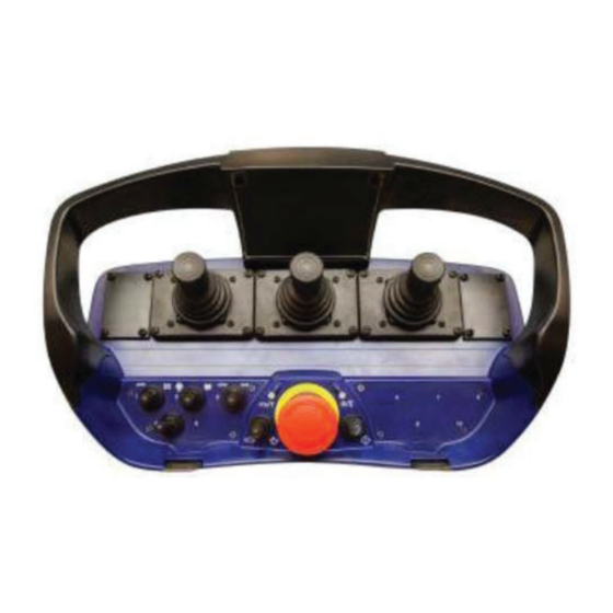
3.2 Scanreco G2 remote control box 3.2.1 General description of the remote control box stop button tumbler switch green diode “ON” push button red diode tumbler switches push buttons tumbler switches buzzer battery 08/02/2019 Manual Part Number: 99906486... -
Page 8: Push Buttons And Tumbler Switches
3.2.2 Push buttons and tumbler switches Engine Safety Number of engine revolutions ”1” Signalling during crane operation. Stop button Engine control Emergency stop during crane operation Engine start-stop ”2” Red diode Engine control Replacement of the battery C + D. Extra functions ON push button Engine throttle control ”3”... -
Page 9: Control Levers
Tumbler switch ”9”: Extra function Yellow push button ”7” Operating symbols Stabilizer mode Operating symbols Tumbler switch ”10”: Extra function Red push button "8" The HDL system G2 InfoCentre. 3.2.3 Control levers Please note Standard configuration of remote control levers, operation direction 08/02/2019 Manual Part Number: 99906486... -
Page 10: Operating Symbols
8 linear control levers Joystick 2-0-2 Joystick 2-2-2 Joystick 3-2-3 3.2.4 Operating symbols 08/02/2019 Manual Part Number: 99906486... - Page 11 Lever sequence, stabilizer functions 8 functions: Stabilizer leg, down Stabilizer beam, extend 6 functions: Stabilizer beam, extend Stabilizer leg, down 4 functions: Stabilizer beam, extend Stabilizer leg, down 08/02/2019 Manual Part Number: 99906486...
- Page 12 Lever sequence, crane functions 8 functions + winch: Basic crane Equipment Click! "10" 7 functions: Equipment Basic crane Click! "10" 08/02/2019 Manual Part Number: 99906486...
- Page 13 6 functions + winch: Basic crane Equipment Click! "10" 6 functions + rotator + grab Basic crane Equipment 6Press Click! and hold! 4 functions Basic crane 08/02/2019 Manual Part Number: 99906486...
-
Page 14: Indications, Remote Control Box
3.2.5 Indications, remote control box Power LED Explanation Micro LED Explanation 08/02/2019 Manual Part Number: 99906486... -
Page 15: Scanreco G2 Radio Remote Control, Infocentre
3.2.6 Scanreco G2 radio remote control, InfoCentre Function keys and diode indications, InfoCentre Green diode ”RUN” Yellow diode "FUNC" Yellow diode Slewing F1 S + T. Load moment 08/02/2019 Manual Part Number: 99906486... - Page 16 Screens, InfoCentre Start-up screens Operation screens. Operation screens. 08/02/2019 Manual Part Number: 99906486...
- Page 17 Operation screens Operation screens appear during normal crane operation, and consist of up to 8 screens with 2 pieces of operation information on each screen. The current screen is indicated by a number in the top right-hand corner (a). b), which graphically indicates the function in question, a One operation information consists of an icon ( numerical value ( c) and a corresponding graphic bar ( d) and a unit indication ( e) e.g.
- Page 18 Operation information. How to change screens / sequence Operation Screens Description Icon Icon no. Numerical value for Unit 08/02/2019 Manual Part Number: 99906486...
- Page 19 08/02/2019 Manual Part Number: 99906486...
- Page 20 Information screens Information screens Description Icon Icon no. Numerical value Unit 08/02/2019 Manual Part Number: 99906486...
- Page 21 Stop screens Stop screens Cause Icon Icon Numerical value for Unit 08/02/2019 Manual Part Number: 99906486...
- Page 22 Indication in case of system errors Error screen Cause Icon Icon Numerical value for Unit 08/02/2019 Manual Part Number: 99906486...
-
Page 23: Remote Control Box In Stand By Mode
Category 2: Reduction of the lifting capacity to 90% Category 3: Stop of the crane Emergency Operation of the Loader Please note! must 3.2.7 Remote control box in stand-by mode 3.3 Scanreco G2 radio controller 08/02/2019 Manual Part Number: 99906486... - Page 24 Emergency operation of the crane The Status Explanation Remote Remote The DV diode Tumbler switch Explanation Status LED display Explanation 08/02/2019 Manual Part Number: 99906486...
-
Page 25: Scanreco G2 Battery And Battery Charger
3.4 Scanreco G2 battery and battery charger 3.4.1 Replacement of the battery Start-up of the radio remote control system 08/02/2019 Manual Part Number: 99906486... -
Page 26: Charging Of The Battery
3.4.2 Charging of the battery 3.4.3 Good advice about the battery 08/02/2019 Manual Part Number: 99906486... -
Page 27: Remote Control Cable
3.5 Remote control cable 3.6 Transmitter system, frequencies 4. Maintenance 08/02/2019 Manual Part Number: 99906486... -
Page 28: Safety Regulations
5. Safety regulations 08/02/2019 Manual Part Number: 99906486... -
Page 29: Starting Up
6. Starting up "Instruction Manual, Loader" RCL 5300 Instruction Manual" 6.1 Starting up from the indicator panel of the RCL (manually controlled stabilizers) 1.8.0 Stabilizer mode Please note: 6.1.1 Start-up of the radio remote control system 08/02/2019 Manual Part Number: 99906486... -
Page 30: Starting Up From The Scanreco G2 Remote Control Box (Radio Remote Controlled Stabilizers)
6.2 Starting up from the Scanreco G2 remote control box (radio remote controlled stabilizers) Stabilizer mode 6.3 Stabilizer mode 6.3.1 Control of the hydraulic stabilizers Operating symbols 08/02/2019 Manual Part Number: 99906486... - Page 31 Operation of the stabilizer beam "extend/retract" Operation of the stabilizer beam "extend/retract" is carried out as follows: 08/02/2019 Manual Part Number: 99906486...
- Page 32 Operation of the stabilizer legs "up/down" Operation of the stabilizer beams and legs at low or high speed Return to crane mode 08/02/2019 Manual Part Number: 99906486...
-
Page 33: Signalling During Crane Operation
7. Signalling during crane operation RCL 5300 Instruction Manual Replacement of battery Troubleshooting 8. Emergency stop during crane operation 9. Stop of the radio remote control system 10. Securing of the remote control box, after operation 08/02/2019 Manual Part Number: 99906486... -
Page 34: Optional Extras
11. Optional extras 11.1 Remote control of optional extras and other crane functions By means of the Scanreco G2 radio remote control system it is possible to remote control optional extras, if any, as well as a range of other functions on the crane. -
Page 35: Micro Operation
11.1.2 Micro-operation 11.1.3 Engine control Engine start-stop tumbler switch tumbler switch Choice of number of engine revolutions tumbler switch tumbler switch tumbler switch 08/02/2019 Manual Part Number: 99906486... -
Page 36: Work Light
Engine throttle control tumbler switch tumbler switch 11.1.4 Work light 11.1.5 Horn 11.1.6 Control of winch on a stowing bracket 08/02/2019 Manual Part Number: 99906486... -
Page 37: Activation Of The Regeneration System
11.1.7 Activation of the regeneration system 08/02/2019 Manual Part Number: 99906486... -
Page 38: Weighing Function
11.1.8 Weighing function Calibration of the system Weighing of load 12. Troubleshooting 08/02/2019 Manual Part Number: 99906486... -
Page 39: Error Code Indications On The Rcl 5300 Indicator Panel
12.1. Error code indications on the RCL 5300 indicator panel Error code in the Type of error Remedy display of the RCL 0.0.1 1.0.8 1.7.0 1.7.1 1.7.2 1.7.3 1.7.4 1.7.5 1.7.6 1.7.7 1.8.0 1.8.1 1.8.2 1.8.3 1.8.4 1.8.5 1.8.6 Manual Remote 1.8.7 08/02/2019... -
Page 40: Error Indications From The Remote Control Box
12.2. Error indications from the remote control box Scanreco G2 radio remote control, InfoCentre. Indication Type of error Remedy 1 flash 2 flashes 3 flashes 4 flashes 5 flashes 6 flashes 7 flashes 8 flashes 13 flashes 08/02/2019 Manual Part Number: 99906486... -
Page 41: Error Indications On The Radio Controller
12.3. Error indications on the radio controller 13. Emergency operation of the crane Troubleshooting Remote control cable Changeover to emergency operation of the crane is carried out as follows: Manual 08/02/2019 Manual Part Number: 99906486... -
Page 42: Marking And Identification
Please note: Remote Remote Marking and identification 08/02/2019 Manual Part Number: 99906486... -
Page 43: Technical Data
15. Technical data General system data Radio controller Remote control box 08/02/2019 Manual Part Number: 99906486... - Page 44 Battery charger Battery 08/02/2019 Manual Part Number: 99906486...
Need help?
Do you have a question about the Scanreco G2 and is the answer not in the manual?
Questions and answers