Table of Contents
Advertisement
Quick Links
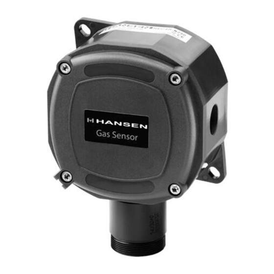
Standard Gas Sensor
Standard Gas Sensor
INTRODUCTION
Hansen Technologies offers a complete line of industrial
quality Gas Detection Sensors, Monitors and Alert
Systems for refrigerants and other common gases.
These state-of-the-art gas detection products utilize a
range of sensing technologies to suit a given application.
Available in several configurations to meet various
application requirements with optimum accuracy and
reliability.
APPLICATIONS
Hansen Gas Sensors are suitable for use in industrial
refr iger ation engine rooms, cold stor age rooms,
processing rooms, truck docks, and for relief valve vent
lines. They are also suitable for use in supermarkets,
and large institutional and commercial buildings.
Typical gas detection applications include Ammonia,
Carbon Dioxide (CO2), Hydrocarbons, HFCs, HCFCs
and CFCs.
ADVANTAGES
Hansen uses a wide variety of sensing technologies
including electrochemical, semiconductor and infrared
sensors to selectively detect most gases. These sensors
continuously determine the level of gas present in the
surrounding environment. The analog outputs (4-20mA
or 0-10V DC) can interface with nearly any existing
monitor, computer or PLC controller.
The sensing elements (except Basic and Extreme Gas
Sensors) are mounted externally on the enclosure. This
helps to provide quick response to potential leaks,
particularly in still air. Electronics are sealed in a NEMA4
enclosure (except Basic Gas Sensor) which protects them
from moisture, dust and the surrounding gases, which in
the case of ammonia can shorten the life of electronics.
The sensing elements are easily replaced.
Gas Sensors have built-in visual and audible alarms.
An auxiliary one amp SPDT relay output is standard.
Testing and recalibration procedures are simple.
Specifications, Applications,
Service Instructions & Parts
GAS DETECTION
SENSORS, MONITORS
& ALERT SYSTEMS
For Refrigerants and
other Common Gases
KEY FEATURES–GAS SENSORS
•
Accurate, fast responding
•
Linear 4-20mA or 0-10V DC output
•
Audible alarm
•
Power indicator
•
SPDT alarm relay (Fail Safe Operation)
•
24V AC/DC low voltage power
•
Shipped factory calibrated and tested
•
CE approved
KEY FEATURES–MONITORS
•
Visual alarm
•
Audible alarm
•
Power indicator
•
Low level alarm relay
•
High level alarm relay
•
Fault relay (HLM6 only)
•
Economical
•
CE approved
KEY FEATURES−GAS ALERT SYSTEM
•
Provides local display and alarm based on
measured target gas level via gas sensor
•
Visual alarm, Amber LED light
•
Audible alarm (mutable)
•
Power indicator, Green
•
Numeric PPM reading
•
Bright LED Display
•
Shipped factory calibrated and tested
Bulletin A100b
JAN 2009
Advertisement
Table of Contents

Summary of Contents for Hansen HLM2
- Page 1 Shipped factory calibrated and tested reliability. • CE approved APPLICATIONS Hansen Gas Sensors are suitable for use in industrial KEY FEATURES–MONITORS refr iger ation engine rooms, cold stor age rooms, processing rooms, truck docks, and for relief valve vent •...
- Page 2 SELECTING GAS SENSOR TYPES PORTABLE GAS DETECTION UNIT Hansen Gas Sensors are available in several types of Portable Gas Detection unit includes enclosures to match the environmental and operating the handheld unit, battery charger, conditions. extension wand, spare filters, voltage...
- Page 3 GAS SENSOR SPECIFICATIONS EXPLOSION BASIC STANDARD HARSH VENT LINE EXTREME PROOF 0ºF TO 105ºF 0ºF TO 105ºF -40ºF TO 105ºF -40ºF TO 105ºF -40ºF TO 105ºF -60ºF TO 105ºF OPER ATING TEMPER ATURE R ANGE (-17ºC TO 40ºC) (-17ºC TO 40ºC) (-40ºC TO 40ºC) (-40ºC TO 40ºC) (-40ºC TO 40ºC)
-
Page 4: Stand Alone Control
STAND ALONE CONTROL The Hansen Gas Sensor can operate as a stand alone device. All that is needed is a 24V AC/DC power supply for the gas sensor and auxiliary devices for light, horn or digital readout, such as the Hansen GAS Alert System. -
Page 5: Sensing Element
WIRING GAS SENSORS customer supplied PLC or computer, refer to Fig. J for wiring details. Install the Hansen Gas Sensor in an area where operating personnel can easily monitor the remote sensor. Refer Hansen recommends backup of gas detection system... - Page 6 ELECTROCHEMICAL SENSOR—AC VOLTAGE (SHOWN WIRED FOR 4-20MA OUTPUT) FIG. A To Monitor or PLC MULTI-WIRE SHIELDED CABLE (GROUND SHIELD AT OTHER END) Factory Default 4-20mA output Relay Output Voltage Selector - "D": 24V DC "A": 24V AC Fail Safe Relay - Relay engerized to normally open HORN JP1 - on: 0-5V / 1-5V / 4-20mA output...
- Page 7 ELECTROCHEMICAL SENSOR—DC VOLTAGE (SHOWN WIRED FOR 4-20MA OUTPUT) FIG. C To Monitor or PLC MULTI-WIRE SHIELDED CABLE (GROUND SHIELD AT OTHER END) Factory Default 4-20mA output Relay Output Voltage Selector - "D": 24V DC "A": 24V AC Fail Safe Relay - Relay engerized HORN to normally open JP1 - on: 0-5V / 1-5V / 4-20mA output...
- Page 8 There are several selectable features included in the LED flashing approximately every second. After five Hansen Gas Sensor. Refer to pages 6 and 7 for the minutes, the green LED stays on continuously, indicating adjustable features. Note the adjustment screws on power to the gas sensor and ready for service.
-
Page 9: Led Logic
(S) so the output reads CALIBRATION PROCEDURES between 4.95 to 5.00 volts DC. Refer to Fig. E for calibration of Hansen sensors. 4. Stop the flow of gas and remove the boot from the sensor element. Verify the sensor voltage output Equipment required: begins to decrease. -
Page 10: Calibration Of Sensors
CALIBRATION OF SENSORS FIG. E ELECTRO CHEMICAL BOARD SHOWN (SEMI CONDUCTOR IS SIMILAR) 1 2 34 5 6 7 8 0-5V DC ZERO POT ADJUSTMENT REGULATING HORN VALVE SPAN POT ADJUSTMENT SENSING ELEMENT BOOT CALIBRATION GAS SENSING ELEMENT REPLACEMENT Basic Sensors Extreme Sensors The Basic Gas Sensor uses a three pin plug-in element Extreme Sensing Elements are internally mounted to... - Page 11 CN11, see Fig. G. The high level SPDT relay may be set for Normal Operation Install the Hansen Gas Detection Monitor on a wall or in (normally closed position with no power) or Fail-Safe an electrical panel in an area where operating personnel Operation (relay energized when power to monitor is will easily monitor the leak detection system.
- Page 12 The voltage range corresponds to the 4-20mA range. (ie. 0.4V DC equals 4mA, 2.0V DC equals 20mA). (HLM2) After the delay, if the input current to any channel is less than 0.9mA the High Level Alarm LED is energized and no For the low level alarm relay setting, measure the voltage audio output.
- Page 13 HLM2 WIRING DIAGRAM FIG. F G A S L E A K M O N IT O R R E M O T E S E N S O R L O W L E V E L A L A R M P O T...
- Page 14 TROUBLESHOOTING GAS MONITORS TROUBLESHOOTING GAS SENSORS Symptom: No lights displayed on panel. Symptom: Sensor green light is off. Cause: Cause: Power failure. Check incoming line. Possible wiring fault between controller and sensor. Check power supply to Controller. Check Tripped circuit breaker or blown fuse on electrical connections between the controller and the supply.
- Page 15 INSTALLATION DIMENSIONS INCHES (MM) HLM2 GAS ALERT SYSTEM 5.26" (134) HIGH LEVEL AUDIBLE ALARM ALARM RESET KEY SWITCH 4.13 (105) .358 DIA (9,1) MOUNTING HOLE 2.07 (53) 6.30" (160) (16) 7.58 6.37 (191) (162) 2.72" (69) 2.93 (78) .173 DIA (4,4)
-
Page 16: Technical Specifications
GAS Alert System WIRING GAS ALERT SYSTEM KEY FEATURES−GAS ALERT SYSTEM • Provides local display and alarm based on The GAS Alert System can be used as a standalone, measured target gas level locally monitored system or as part of a larger gas •... - Page 17 Power Supply Cable Shield Shield At This End 24V AC/DC Multi-Wire EARTH GRD Cable Shield JUMPER INSTALLED. TYPICAL WIRING DIAGRAM WITH HANSEN HLM6 MONITOR FIG. I 120V: GMC-315mA 250V 230V: GMC-160mA 250V HORN FUSE LOW LEVEL ALARM POT - LINE...
- Page 18 PLC 4 PT. ANALOG IN MODULE (CURRENT) FIG. J *REMOTE SENSOR GREEN V +V NO COM NC Multi-Wire Cable Shield INPUT #1 Power Supply INPUT #2 24V AC/DC INPUT #3 INPUT #4 EARTH GRD ANALOG GND REMOTE SENSOR * Wiring is the same for AC or DC Power Supply. REMOTE SENSOR Voltage selector must match external power supply.
- Page 19 31-0082 GAS DETECTION MONITORS R410 5,000 31-0130 Catalog No. Description GAS SENSOR ACCESSORIES HLM2 Two Channels; internal audible alarm HLM6 Six Channels; external audible alarm Catalog No. Description Note: Specify voltage 120V AC or 220V AC. 31-1000 Sensor Calibration Kit...
-
Page 20: Warranty
Semiconductor * Board mounted sensing element for obsolete standard gas sensor. CAUTION Hansen Gas Detection Sensors, Monitors and Alert Systems have been designed for refrigeration systems. These instructions must be completely read and understood before selecting, using or servicing Hansen valves.
Need help?
Do you have a question about the HLM2 and is the answer not in the manual?
Questions and answers