
Related Manuals for Siemens ACUSON Antares


Summary of Contents for Siemens ACUSON Antares
- Page 1 ACUSON Antares Ultrasound Imaging System [1] Instructions for Use S ie me ns M edi cal Sol uti on s USA , In c . 10033049-ABS-001-01...
- Page 3 CIDEX, CIDEX Plus, CIDEX OPA, Milton, Virkon, Gigasept FF, and STERRAD are trademarks of their respective owners. Siemens reserves the right to change system specifications at any time. [ 1 ] I N S T R U C T I O N S...
- Page 4 [ 1 ] I N S T R U C T I O N S F O R U S E...
- Page 5 Technical description of the ultrasound system. Note: Not all features and options described in this publication are available to all users. Please check with your Siemens representative to determine the current availability of features and options. Refer to the Accessories and Options chapter of the System Reference for a list of system-specific features and options, including transducers.
- Page 6 [ 1 ] I N S T R U C T I O N S F O R U S E...
- Page 7 About This Manual The Instructions for Use consists of two volumes: [1] Instructions for Use The [1] Instructions for Use includes both a general overview and a technical description of the ultrasound imaging system. This manual contains detailed information on the safety and care of the ultrasound system and its transducers.
- Page 8 Conventions Conventions used throughout this manual are listed below. Take a moment to familiarize yourself with these conventions. Warnings, Cautions, and Notes WARNING: Warnings are intended to alert you to the importance of following the correct operating procedures where risk of injury to the patient or system user exists.
- Page 9 Special Terms Special terms are indicated in boldface italicized text and are accompanied by a brief description on their first use in the manual. Example: When the trackball is used to make menu selections, it is pointer assigned to the function.
- Page 10 v i i i [ 1 ] I N S T R U C T I O N S F O R U S E...
-
Page 11: Table Of Contents
1 Introduction System Overview ....................3 Configurations ....................4 Language Formats.................. 4 Transducers.................... 4 Intended Use....................... 5 Operating Modes....................6 Image Screen Layout ..................7 Screen Saver ....................7 Sample Image Screen ................8 Image Task Card..................9 Documentation Devices................... 10 Patient Data Management................ - Page 12 1 I n t r o d u c t i o n 1 - 2 [ 1 ] I N S T R U C T I O N S F O R U S E...
-
Page 13: System Overview
1 I n t r o d u c t i o n System Overview The Antares system is a high-resolution, digital, broadband diagnostic ultrasound imaging system. In addition to 2D-mode and M-mode imaging, the system is integrated with pulsed Doppler, Color Doppler, and Power Doppler imaging. -
Page 14: Configurations
1 I n t r o d u c t i o n Configurations The Antares system is available in 100V~, 115V~, and 230V~ mains voltage. [1] Instructions for Use System/Hardware Language Formats Options Ch 6 Operating system software and control panel overlays are available in System Reference English, German, French, Spanish, and Italian languages. -
Page 15: Intended Use
1 I n t r o d u c t i o n Intended Use System Reference Caution: In the United States of America, federal law restricts this device to sale or use by, or on the order of, a physician. Listing of Transducers The Antares ultrasound system supports the following applications:... -
Page 16: Operating Modes
1 I n t r o d u c t i o n Operating Modes 2D-mode: 2D-mode is the default setting. When the system is powered on, the image screen displays in 2D-mode. M-mode: Full screen M-mode display and 2D/M-mode display are available. -
Page 17: Image Screen Layout
1 I n t r o d u c t i o n Image Screen Layout The monitor on the ultrasound system displays clinical images together with important operating parameters, patient data, and control commands. The primary tasks during an exam are grouped into task cards that follow the high-level workflow of an exam. -
Page 18: Sample Image Screen
1 I n t r o d u c t i o n Sample Image Screen Example of a typical image screen during 2D-mode with color imaging. Color bar Task card and display. . The available task cards are Image, Calcs, Review, and Compose. region of interest 2 Color Doppler (ROI). -
Page 19: Image Task Card
1 I n t r o d u c t i o n Image Task Card [2] Instructions for Use IMAGE: Parameter menu Ch 1 Group box Ch 1 Drop-down menu Ch 1 Example of an image screen with the Image task card active. -
Page 20: Documentation Devices
EN 60601-1-1 and IEC 60601-1-1. Siemens can only guarantee the performance and safety of the devices listed in the System Reference. If in doubt, consult Siemens service department or your local Siemens representative. -
Page 21: Patient Data Management
1 I n t r o d u c t i o n Patient Data Management Patient data consists of saved or printed ultrasound images and printed patient reports. Patient data is saved to the ultrasound system internal hard disk (local database). -
Page 22: Measurements And Reports
1 I n t r o d u c t i o n Measurements and Reports The measurement function contains measurement labels, measurement [2] Instructions for Use tools, pictograms, and reports for all of its intended uses. CALCS: Measurements and System Presets Reports Ch 1... - Page 23 Caring for the Ultrasound System ..............20 Daily Checklist ..................... 20 Maintenance....................21 Repair ....................21 Siemens Authorized Care..............21 Caring for Documentation and Storage Devices.......... 23 Caring for the Battery Pack................23 Battery Pack Replacement and Disposal..........24 Battery Pack Location................25 Removing the Battery Pack ..............
- Page 24 2 S a f e t y a n d C a r e Caring for Transducers..................38 Protective Case ................... 39 Storage....................39 Repair ....................39 Cleaning and Disinfecting Transducers............40 IPX8 Immersion Levels................. 42 Approved List of Disinfectants ............. 43 Sterilizing Transducers VF13-5SP ............
-
Page 25: Operating Safety And Environment
2 S a f e t y a n d C a r e Operating Safety and Environment Do not operate the ultrasound imaging system until you fully understand the safety considerations and procedures presented in this manual. System Symbols The table below is provided for your identification of important symbols [1] Instructions for Use located on the ultrasound imaging system and transducers:... - Page 26 2 S a f e t y a n d C a r e Symbol Explanation Ethernet 10/100BaseT Connection Audio Video Luma/Color Composite Video Video – Red, Green, Blue Control Panel Light or Indicator Light Yellow Indicator Light Status Indicator for DC Power Good (Green) or Green Indicator Light Printer Connection Type BF Defibrillator-proof Patient Connection...
- Page 27 2 S a f e t y a n d C a r e Symbol Explanation Signal Input Signal Output PS2 Port/Bar Code Scanner Footswitch Connector Equipotential Connection Protective Earth Ground Do not install wet Location of Air Filter Insert this way Battery Recycle Ni-MH battery Ni-MH...
- Page 28 2 S a f e t y a n d C a r e Symbol Explanation Brake Engaged Brake Released Direction/Steer Lock Manufacturer's declaration of product compliance with applicable EEC directive(s) and the European 0123 notified body DEMKO-Denmark approval mark UL symbol for listing as recognized components for Canada and United States of America E170920...
- Page 29 2 S a f e t y a n d C a r e Symbol Explanation Identifies voltage, frequency, and current rating of system configuration for MAINS. 115V~, 50/60 Hz, 12A maximum draw, 15A MAINS breaker. Identifies voltage, frequency, and current rating of system configuration for MAINS.
-
Page 30: Labels
2 S a f e t y a n d C a r e Labels X-ray shielding notice System warning label, identification label, and certification labels Location of labels on the ultrasound system (example). 2 - 8 [ 1 ] I N S T R U C T I O N S F O R U S E... - Page 31 2 S a f e t y a n d C a r e Example of system warning label, identification label, and certification labels. 2 - 9 [ 1 ] I N S T R U C T I O N S F O R U S E...
- Page 32 2 S a f e t y a n d C a r e 1 Product name 2 Manufacturing date 3 Model number barcode 4 Model number 5 Serial number barcode 6 Serial number 7 Product status number Example of system serial number (overlays system warning label). Example of X-ray shielding notices: "The X-ray radiation of this unit is sufficiently shielded."...
-
Page 33: Biohazard Considerations
The ultrasound energy emitted by the transducer easily penetrates the fontanels of the infant. WARNING: Siemens makes every effort to manufacture safe and effective transducers. You must take all necessary precautions to eliminate the possibility of exposing patients, operators, or third parties to hazardous or infectious materials. -
Page 34: Acoustic Output Mechanical And Thermal Indices
2 S a f e t y a n d C a r e Acoustic Output Mechanical and Thermal Indices WARNING: Ultrasound procedures should be used for valid reasons, for the shortest period of time, and at the lowest mechanical/thermal index setting necessary to produce clinically acceptable images. -
Page 35: Transmit Power Control
2 S a f e t y a n d C a r e Transmit Power Control Adjust the transmit power and the corresponding acoustic pressure [1] Instructions for Use delivered through the transducer to the patient by using the designated Functions Affecting control on the ultrasound system. -
Page 36: Imaging Functions That Change Acoustic Output
2 S a f e t y a n d C a r e Imaging Functions that Change Acoustic Output WARNING: Observe the real-time display of mechanical and thermal indices (MI/TI) at all times. In addition to the adjustment of the transmit power, adjustment of the following imaging functions and/or controls may affect the acoustic output: Automatic Time-out Imaging Mode... -
Page 37: Transducer Surface Temperature Limits
2 S a f e t y a n d C a r e Transducer Surface Temperature Limits The following table provides the maximum surface temperature of the transducers compatible with the system. Maximum surface temperatures are in accordance with IEC 60601-2-37. Maximum Temperature Transducer Still Air... -
Page 38: Electrical Safety
System Reference Caution: To ensure proper grounding and leakage current levels, it is the policy of Siemens to have an authorized Siemens representative or Siemens approved Documentation third party perform all on-board connections of documentation and storage Devices Ch 5 devices to the ultrasound system. -
Page 39: Level Of Protection Against Electrical Shock System
2 S a f e t y a n d C a r e Level of Protection Against Electrical Shock System According to EN 60601-1 and IEC 60601-1, the system provides a "Level of Protection Against Electrical Shock" of "Type B." The Type B icon is located on the system. -
Page 40: Possible Combinations With Other Equipment
EN 60601-1-1 and IEC 60601-1-1. Siemens can only guarantee the performance and safety of the devices listed in the System Reference. If in doubt, consult Siemens service department or your local Siemens representative. -
Page 41: Maintaining Data Integrity
2 S a f e t y a n d C a r e Maintaining Data Integrity Important Information To ensure data integrity: To prevent the loss of data that results from power failures and other system "down" occurrences, you must archive important data, such as patient records, onto an external recording media, such as a CD or a network. -
Page 42: Caring For The Ultrasound System
2 S a f e t y a n d C a r e Caring for the Ultrasound System It is the responsibility of the user to verify that the ultrasound system is safe for diagnostic operation on a daily basis. Each day, prior to using the system, perform each of the steps in the Daily Checklist. -
Page 43: Maintenance
Perform inspections and maintenance at the prescribed intervals to avoid worn and hazardous parts due to wear. Contact the Siemens service department for information regarding the required maintenance. As manufacturers and installers of ultrasound equipment, Siemens cannot... - Page 44 EN 60601-1-1 and IEC 60601-1-1. Siemens can only guarantee the performance and safety of the devices listed in the System Reference. If in doubt, consult Siemens service department or your local Siemens representative.
-
Page 45: Caring For Documentation And Storage Devices
2 S a f e t y a n d C a r e Caring for Documentation and Storage Devices For information on the care of an optional documentation or storage device, refer to the manufacturer's operating instructions that accompanied the device. -
Page 46: Battery Pack Replacement And Disposal
2 S a f e t y a n d C a r e Battery Pack Replacement and Disposal Replace the battery pack when it is no longer able to hold a charge. When the system is used with the Mobile QuikStart option and frequently disconnected from the AC power (for a duration of greater than four to eight hours), replace the battery every 12 to 18 months. -
Page 47: Battery Pack Location
2 S a f e t y a n d C a r e Battery Pack Location The battery pack is located under the storage bin cover, within a recess on the right rear panel of the ultrasound system. The storage bin cover must be removed to access the battery pack. - Page 48 2 S a f e t y a n d C a r e To remove the storage bin cover: 1. Grasp the cover by the top right edge, above the battery location, and gently pull to unsnap the first of four fastener pins from its receptacle. 2.
-
Page 49: Removing The Battery Pack
2 S a f e t y a n d C a r e Removing the Battery Pack Caution: When removing the battery pack, be careful not to pull or otherwise strain the wires in the cable connecting the battery to the ultrasound system because doing so can damage the battery pack and the ultrasound system. -
Page 50: Installing A Battery Pack
2 S a f e t y a n d C a r e Installing a Battery Pack Caution: There is only one correct orientation for attaching the battery connector. Do not force or twist the connector because doing so can damage the battery pack and the ultrasound system. -
Page 51: Battery Pack Disposal
United States of America – Rechargeable Battery Recycling Corporation (RBRC) Note: If a local battery recycling program does not exist then return used batteries to the address below. When returning batteries, label the package: "Attn.: Battery Recycling". Siemens AG Medical Engineering TD ML RE Betr.: Battery Recycling... -
Page 52: Cleaning And Disinfecting
2 S a f e t y a n d C a r e Cleaning and Disinfecting You must take all necessary precautions to eliminate the possibility of exposing patients, operators, or third parties to hazardous or infectious materials. Use universal precautions when cleaning and disinfecting. You should treat all portions of the ultrasound system that come in contact with human blood or other body fluids as if they were known to be infectious. - Page 53 2 S a f e t y a n d C a r e To clean the holders for transducers and coupling gel: 1. Remove the holder from the ultrasound system. a. Reach under the holder to locate the tab on the holder. The tab extends below the point of attachment to the ultrasound system.
- Page 54 2 S a f e t y a n d C a r e To clean the trackball: Caution: Do not drop or place foreign objects inside the trackball assembly because doing so may affect the trackball operation and damage the ultrasound system.
- Page 55 2 S a f e t y a n d C a r e 2. Clean the bezel, gasket, and trackball with a cotton swab or lint-free pad moistened with mild detergent solution. 3. Clean the inside of the trackball assembly, particularly the X and Y encoders and the idler wheel, using a cotton swab moistened with mild detergent solution.
-
Page 56: Cleaning The Air Filters
2 S a f e t y a n d C a r e Cleaning the Air Filters The ultrasound system has removable, washable air filters. The filters must be cleaned regularly to maintain proper system cooling. Check the air filters weekly, and clean as needed. - Page 57 2 S a f e t y a n d C a r e To remove and clean the back panel air filter: Caution: Do not scrub, stretch, or bend the filter, or apply heat to the filter, as doing so could damage the filter. 1.
- Page 58 2 S a f e t y a n d C a r e 3. Remove the air filter from the tray. 1 Air filter tray 2 Hook and loop fasteners 3 Air filter 4 Flat side of air filter Removing/replacing the air filter.
- Page 59 2 S a f e t y a n d C a r e To remove and clean the input/output panel air filter: Caution: Do not scrub, stretch, or bend the filter, or apply heat to the filter, as doing so could damage the filter. 1.
-
Page 60: Caring For Transducers
Caution: Transducers are sensitive instruments – irreparable damage may occur if they are dropped, knocked against other objects, cut, or punctured. Do not attempt to repair or alter any part of a transducer, contact your local Siemens representative. Caution: To avoid cable damage, do not roll the ultrasound system over transducer cables. -
Page 61: Protective Case
Ch 6 Repair Do not attempt to repair or alter any part of the transducer. Contact your service representative at Siemens immediately if a transducer appears to be damaged or malfunctions in any way. 2 - 3 9 [ 1 ]... -
Page 62: Cleaning And Disinfecting Transducers
WARNING: Disinfectants and cleaning methods listed are recommended by Disinfectants 2-43 Siemens for compatibility with product materials, not for biological effectiveness. Refer to disinfectant label instructions for guidance on disinfection efficacy and appropriate clinical uses. Caution: Do not sterilize transducers using hot steam, cold gas, or Ethylene Oxide (EOG) methods. - Page 63 2 S a f e t y a n d C a r e To clean and disinfect a transducer: 1. Disconnect the transducer from the system. 2. Moisten a clean gauze pad with water and wipe the transducer to remove any gel or particles remaining on the transducer.
-
Page 64: Ipx8 Immersion Levels
2 S a f e t y a n d C a r e IPX8 Immersion Levels Caution: To avoid damage to the transducer, observe the immersion levels indicated for each transducer type. Note: Transducers meet Ingress Protection level IPX8 of EN 60539 and IEC 60539 to the depth of the immersion line shown in the illustration. -
Page 65: Approved List Of Disinfectants
2 S a f e t y a n d C a r e Approved List of Disinfectants The following matrix provides a list of approved disinfectants for all transducers. Note: The approved disinfectants, Cidex OPA and Gigasept FF, may discolor transducer housings, including the face of the transducer. -
Page 66: Sterilizing Transducers Vf13-5Sp
2 S a f e t y a n d C a r e Sterilizing Transducers VF13-5SP Caution: The transducers have been designed and tested to be able to withstand sterilization as recommended by the manufacturer of the sterilization system. Carefully follow the sterilization manufacturer's instructions. The STERRAD®... -
Page 67: Caring For Transducer Accessories
A sterile, non-pyrogenic transducer sheath must be in place during procedures requiring sterility. Note: Siemens recommends that you follow all instructions provided by manufacturers of sterile goods (transducer sheaths) to ensure proper handling, storage, and cycling of all sterile goods. -
Page 68: Gel Pad
2 S a f e t y a n d C a r e Gel Pad Before use, examine the gel pad for any material flaws. Thinning, bulging, or brittleness of the material indicates damage. Any product showing flaws should not be used. Storage Do not store the gel pads below 40°F (5°C) nor above 135°F (57°C). -
Page 69: Needle Guide Bracket Kits
When the biopsy adapter is transported to a different hospital or clinic or is sent to your Siemens representative for repair, be sure to sterilize it and keep it in the carrying case for transportation to prevent infection. Storing or Transporting the CH4-1, C7F2/C5F1, SG-1, SG-2, SG-3, SG-4, and SG-5 Bracket Kits Refer to the in-box instructions for storage and transportation information. -
Page 70: Cleaning, Disinfecting, And Sterilizing Transducer Accessories
2 S a f e t y a n d C a r e Cleaning, Disinfecting, and Sterilizing Transducer Accessories [2] Instructions for Use WARNING: Ensure the accessories for a transducer are properly cleaned, sterilized, or disinfected as appropriate before each use to avoid possible RESOURCES: patient contamination. - Page 71 2 S a f e t y a n d C a r e EC-1 Needle Guide Bracket Kit for Endocavity Transducers WARNING: The EC-1 Needle Guide Bracket kit is packaged non-sterile. Sterilize this product prior to its first use. Prior to sterilization, clean the bracket assembly.
- Page 72 2 S a f e t y a n d C a r e CH4-1, C7F2/C5F1, SG-1, SG-2, SG-3, SG-4, and SG-5 Bracket Assemblies WARNING: The needle guide is packaged sterile and is a single-use item. Do not use if the packaging indicates signs of tampering or if the expiration date has passed.
- Page 73 3 System Controls Control Panel ...................... 5 Control Panel Overlays .................. 5 Control Panel Lighting ................... 6 Mode Controls....................6 2D......................6 D......................7 C......................7 M......................8 Trackball Controls ..................9 Select ..................... 9 Update View..................10 Priority Tool ..................11 Next......................
- Page 74 3 S y s t e m C o n t r o l s Keyboard ......................20 Shortcut Keys ....................20 Function Keys....................21 Patient ....................21 Report ....................21 Browser....................21 Film ...................... 21 Presets ....................21 Help...................... 21 Other Alphanumeric Keys................
- Page 75 3 S y s t e m C o n t r o l s Image Task Card ....................26 Parameter Menu Selections ................ 26 2D-Mode Parameter Menu Selections ..........26 M-Mode Parameter Menu Selections ..........28 Color Parameter Menu Selections............29 Power Parameter Menu Selections............
- Page 76 3 S y s t e m C o n t r o l s Filming Screen....................60 Filming Screen Tools ................... 60 Filming Screen Tab Card................61 Layout Tab.................... 61 Images Tab................... 61 Camera Tab ..................62 Filming Shortcut Menus ................62 Film Job Management Selections ............
-
Page 77: Control Panel
3 S y s t e m C o n t r o l s Control Panel The controls and keys for all imaging modes, parameters, documentation, and on-screen selections are designed to promote quick learning and recognition of the controls and keys on the control panel. Control Panel. -
Page 78: Control Panel Lighting
3 S y s t e m C o n t r o l s Control Panel Lighting The system provides two levels of lighting on the control panel: when the ultrasound imaging system is in use, the control panel is back-lit, and when a control or key is active, the lighting intensity of the active control or key is increased. - Page 79 3 S y s t e m C o n t r o l s The D control is a multi-function control. Use the system presets to select the default action of the D control (cursor on/off) and to configure the system to initiate Cursor Audio Mode whenever the D control is pressed.
- Page 80 3 S y s t e m C o n t r o l s The M control is a multi-function control. Use the system presets to select the default action of the M control (cursor on/off). Cursor Off – Pressing the M control activates M-mode and displays the M-mode.
-
Page 81: Trackball Controls
3 S y s t e m C o n t r o l s Trackball Controls The trackball is the main interactive control used with on-screen objects. Use the trackball to position tools, such as the ROI, Doppler cursor, and measurement calipers, and to make selections from the on-screen menus. -
Page 82: Update View
3 S y s t e m C o n t r o l s Update View The function of the UPDATE VIEW key is dependent on the active mode and the active task card. Active Task Card Function Description Image Enables TEQ (optional feature) when the UPDATE VIEW Update View. -
Page 83: Priority Tool
3 S y s t e m C o n t r o l s Priority Tool The PRIORITY TOOL key changes which tool is currently under the control of the trackball. A tool can be a mode tool (2D FOV, D Gate, M Line, C ROI), or a set of calipers. -
Page 84: Next
3 S y s t e m C o n t r o l s Next The NEXT key cycles through the functions of the tool currently under control of the trackball. For example, during Doppler, the active mode tool is D Gate. -
Page 85: Archiving Controls
3 S y s t e m C o n t r o l s Archiving Controls Use the archiving controls to access documentation and storage devices for printing, storing, or retrieving stored images. Freeze Freezes the image or sweep. When you suspend real-time imaging, the system activates CINE. -
Page 86: Cine Wheel
3 S y s t e m C o n t r o l s CINE Wheel Reviews images in a continuous display of stored data in a forward or backward direction, or frame-by-frame, either forward or backward. Active Task Card Function Description Review CINE images by slowly rotating the Image... -
Page 87: Print/Store
3 S y s t e m C o n t r o l s Print/Store The control panel has two PRINT/STORE keys. Each PRINT/STORE key Print/Store prints and/or saves an image as configured in the system presets. Print/Store. Print/Store. Image Controls Depth Changes the imaging depth. -
Page 88: Zoom
3 S y s t e m C o n t r o l s Zoom Changes the image magnification. Pressing the ZOOM control magnifies the image. Rotating the ZOOM control clockwise increases the zoom factor; rotating the control counterclockwise decreases the zoom factor. During 3-Scape or fourSight, magnification is applied to all quadrants. -
Page 89: Universal 2
3 S y s t e m C o n t r o l s UNIVERSAL 2 A mode-dependent control that performs different functions based on the active task card. Active Task Card Function Description Image Adjusts the settings of parameters depending on the active imaging mode. -
Page 90: Universal 1
3 S y s t e m C o n t r o l s UNIVERSAL 1 A mode-dependent control that performs different functions based on the active task card. Active Task Card Function Description Image Adjusts the settings of parameters depending on the active imaging mode. -
Page 91: Other Controls
3 S y s t e m C o n t r o l s Other Controls Speaker Microphone Rotating the control adjusts the speaker volume for the system. Pressing the control turns the microphone on and off during VCR recording. Speaker Microphone. -
Page 92: Keyboard
3 S y s t e m C o n t r o l s Keyboard Use the alphanumeric keyboard for entering patient data, annotating clinical images, and configuring the system. The keyboard slides out from under the control panel and is arranged like a standard computer keyboard with the addition of function keys, standard control keys, and other alphanumeric keys. -
Page 93: Function Keys
3 S y s t e m C o n t r o l s Function Keys The function keys, located in a row across the top of the keyboard, access the Patient Registration form, patient Report, patient browser, Filming screen, system presets, and the online Help. -
Page 94: Other Alphanumeric Keys
3 S y s t e m C o n t r o l s Other Alphanumeric Keys Annotation Cursor Activates the annotation function. Roll the trackball to position the text cursor and then use the keyboard to enter text. Text A, Text B, Text C, Text D Annotation Cursor. -
Page 95: Clear Line
3 S y s t e m C o n t r o l s Clear Line Deletes all text annotations on the line where the text cursor is positioned. Picto Clear Line. Displays the first available pictogram for the selected application. To remove the pictogram selection from the image screen, select the Delete current pictogram button on the lower left of the screen when the Calcs task card is active. -
Page 96: Backspace
3 S y s t e m C o n t r o l s Backspace Deletes one character at a time from right to left. Caps Lock Backspace. Locks all keyboard letter keys in uppercase. Note: The green LED next to the key is illuminated when this function is enabled. Caps Lock. -
Page 97: Footswitch
3 S y s t e m C o n t r o l s Footswitch When you assign a function to a footswitch pedal, you can activate the assigned function using the pedal instead of the associated key or on-screen selection. -
Page 98: Image Task Card
3 S y s t e m C o n t r o l s Image Task Card The Image task card is used for selecting the imaging mode and the image format and for optimizing the settings such as dynamic range, persistence, and edge enhancement or for selecting an exam type or transducer that contains pre-configured, optimized settings. - Page 99 3 S y s t e m C o n t r o l s Menu Selection Tool Tip Description Settings Persist Persistence Increasing Persistence creates a visible smoothing Dependent on effect by maintaining lines of image data for each transducer and frame of imaging.
-
Page 100: M-Mode Parameter Menu Selections
3 S y s t e m C o n t r o l s M-Mode Parameter Menu Selections Menu Selection Tool Tip Description Settings (current Transmit Changes the transmit frequency of an active Transducer- setting) Frequency multi-frequency transducer in M-mode. dependent Sweep Sweep Speed... -
Page 101: Color Parameter Menu Selections
3 S y s t e m C o n t r o l s Color Parameter Menu Selections Menu Selection Tool Tip Description Settings Adjusts the scale factor of the Pulsed Repetition Transducer- Frequency (PRF). dependent Flow Flow State Optimizes hemodynamic flow conditions. -
Page 102: Power Parameter Menu Selections
3 S y s t e m C o n t r o l s Power Parameter Menu Selections Menu Selection Tool Tip Description Settings Adjusts the scale factor of the Pulsed Repetition Transducer- Frequency (PRF). dependent Flow Flow State Optimizes hemodynamic flow conditions. -
Page 103: Doppler Parameter Menu Selections
3 S y s t e m C o n t r o l s Doppler Parameter Menu Selections Menu Selection Tool Tip Description Settings Adjusts the scale factor of the Pulsed Repetition Transducer- Frequency (PRF). dependent Baseline% Baseline Shifts the spectral baseline position. Invert Invert Reverses the spectrum relative to the baseline. -
Page 104: Drop-Down Menus And Group Boxes
3 S y s t e m C o n t r o l s Drop-Down Menus and Group Boxes In addition to the Parameter menu, the Image task card contains imaging selections in a drop-down menu or a group box. Transducer Drop-Down Menu Allows you to activate a transducer different from the one activated during [1] Instructions for Use... - Page 105 3 S y s t e m C o n t r o l s Imaging Selections [2] Instructions for Use IMAGE: Biopsy Ch 6 Menu Selection Tool Tip Description Displays 2D format options. SieScape Displays selections for the SieScape Panoramic Imaging option. 3-Scape Displays selections for the 3-Scape Imaging option.
- Page 106 3 S y s t e m C o n t r o l s Doppler During Doppler, the group box contains drop-down menus for determining [2] Instructions for Use the Update style of your 2D image and Doppler spectrum. IMAGE: Doppler functions Ch 4...
- Page 107 3 S y s t e m C o n t r o l s SieScape Imaging When this option is installed on your system, the Imaging group box contains selections and a speed indicator for use in acquisition of a SieScape image.
- Page 108 3 S y s t e m C o n t r o l s 3-Scape Imaging When this option is installed on your system, the Imaging group box contains selections for use in acquisition of a 3-Scape volume. Menu Selection Tool Tip Description...
-
Page 109: Physio Group Box
3 S y s t e m C o n t r o l s Physio Group Box When this option is installed on your system, the Physio group box provides ECG selections. Physio Control Layout Icon Selection Description Phys Swp Specifies the physio sweep speed. -
Page 110: Vcr Group Box
3 S y s t e m C o n t r o l s VCR Group Box When this option is installed on your system, the VCR group box allows you to control the VCR directly from the Image task card. VCR Control Layout Note: A menu selection can be an icon and/or text. -
Page 111: Foursight 4D Imaging
3 S y s t e m C o n t r o l s four Sight 4D Imaging four Sight Parameter Menu Selections The fourSight Parameter menu includes general selections and 2D-mode parameters. These selections display on the Image task card during acquisition and when acquisition is paused. - Page 112 3 S y s t e m C o n t r o l s four General Selections for Sight Imaging Menu Selection Tool Tip Description Settings Quadrant Active Quadrant Selects (activates) a quadrant. A, B, C, D Rotate Volume Rotation Rotates the volume to the selected angle in degrees.
- Page 113 3 S y s t e m C o n t r o l s four 2D-Mode Parameters for Sight Imaging Note: A Parameter menu may have two pages of selections. To access the menu selections, roll the trackball to the Page 1 of 2 indicator or the Page 2 of 2 indicator on the Parameter menu and then press the SELECT key.
- Page 114 3 S y s t e m C o n t r o l s Menu Selection Tool Tip Description Settings Opacity Opacity Adjusts the percentage of opacity in the volume to 0 to 100 smooth image contours. Smooth Smoothing Adjusts the percentage of smoothing to smooth the 0 to 100 data in the volume quadrant.
-
Page 115: Foursight Editing Group Box
3 S y s t e m C o n t r o l s four Sight Editing Group Box Use the Editing group box to define an area within the volume to be removed. These selections are available during acquisition, when acquisition is paused, and for retrieved volumes. -
Page 116: Foursight Animation Group Box
3 S y s t e m C o n t r o l s four Sight Animation Group Box These selections are available when acquisition is paused and for retrieved volumes. Menu Selection Tool Tip Description Settings Automatic Automatically rotates the volume according to the selected range, speed, and axis. -
Page 117: Cine Graphics
3 S y s t e m C o n t r o l s CINE Graphics CINE bar During CINE playback, a displays on-screen below the image. This CINE bar represents the status of the CINE memory buffer and contains the following elements: 1 Left CINE marker –... -
Page 118: Calcs Task Card
3 S y s t e m C o n t r o l s Calcs Task Card The Calcs task card is used during the Measurement function for making measurements and calculations. When activated, group boxes for Measurements, Labels, and Text/Picto (Text) display on the left side of the screen, including menus for measurement tools, measurement labels, and pictograms. -
Page 119: Text/Picto (Text) Group Box
3 S y s t e m C o n t r o l s Text/Picto (Text) Group Box You can display the Text/Picto group box on the Calcs task card, and you can display the Text group box on the Image task card. Use the system presets to automatically display the Text/Picto (Text) group box when you freeze the image. -
Page 120: Basic Measurement Tools 2D-Mode
3 S y s t e m C o n t r o l s Basic Measurement Tools 2D-Mode Tool Icon 2D-Mode Measurements Distance Ellipse Trace Basic Measurement Tools M-Mode Tool Icon M-Mode Measurements Distance Heart Rate Slope Time Basic Measurement Tools Doppler Tool Icon Doppler Measurements Velocity/Frequency... -
Page 121: Review Task Card
3 S y s t e m C o n t r o l s Review Task Card Note: Multiple-frame images, such as clips and volumes, cannot be printed or copied to the Filming screen. The Review task card allows you to review images stored during the current examination. -
Page 122: Image Selection Tools
3 S y s t e m C o n t r o l s Image Selection Tools Icon Tool Function Single Select When a new image is selected, any previously selected image is deselected. Multiple When a new image is selected, any previously selected image remains Select selected. -
Page 123: Compose Task Card
3 S y s t e m C o n t r o l s Compose Task Card The Compose task card allows you to edit data acquired with system [1] Instructions for Use feature options. It provides tools for manipulating or rotating the Protocol Group Box 3-38 images/volumes. -
Page 124: 3-Scape Parameter Menu Selections (Option)
3 S y s t e m C o n t r o l s 3-Scape Parameter Menu Selections (Option) The 3-Scape Parameter menu includes general selections and mode-specific selections. General selections apply to the entire 3-Scape data set while mode-specific selections apply to data of the specified mode only. - Page 125 3 S y s t e m C o n t r o l s Menu Selection Tool Tip Description Settings Format Change display Selects a display format: format 1:1—Displays the selected quadrant only, in full- screen display format. 4:1—Displays all four quadrants on the screen. 2:1—Displays two quadrants on the screen: Quadrant A (the acquisition plane) on the left and the volume on the right.
-
Page 126: 2D-Mode-Specific Selections For 3-Scape Imaging
3 S y s t e m C o n t r o l s 2D-Mode-Specific Selections for 3-Scape Imaging Menu Selection Tool Tip Description Settings Opacity (current Rendering Mode Renders the 2D-mode data in the volume using the setting) selected rendering method: MinIP Opacity—Smoothes image contours, creating a soft,... - Page 127 3 S y s t e m C o n t r o l s Menu Selection Tool Tip Description Settings Low Th Low Threshold Sets the low threshold for the opacity curve. Removes 0 to 254 2D-mode data (voxels) that have values lower than the selected threshold.
-
Page 128: Power Mode-Specific Selections For 3-Scape Imaging
3 S y s t e m C o n t r o l s Power Mode-Specific Selections for 3-Scape Imaging Menu Selection Tool Tip Description Settings Opacity (current Color Rendering Renders the Power mode data in the volume using the setting) selected rendering method: Mode... - Page 129 3 S y s t e m C o n t r o l s Menu Selection Tool Tip Description Settings High Th High Threshold Sets the high threshold value for the opacity curve. 1 to 255 Assigns a constant opacity value to all voxels at or above the selected threshold.
-
Page 130: 3-Scape Editing Group Box (Option)
3 S y s t e m C o n t r o l s 3-Scape Editing Group Box (Option) Use the Editing group box to define an area within the volume to be removed. The system removes displayed data only (2D-mode and/or Power mode data). -
Page 131: 3-Scape Animation Group Box (Option)
3 S y s t e m C o n t r o l s 3-Scape Animation Group Box (Option) Menu Selection Tool Tip Description Settings Automatic Automatically rotates the volume according to the selected Rotation range, speed, and axis. Wireframe Enables or disables the display of the wireframe in the volume quadrant. -
Page 132: Filming Screen
3 S y s t e m C o n t r o l s Filming Screen The Filming screen allows you to preview images before printing, customize print settings for images, and print images. The Filming screen has selections for displaying the next or previous page, setting the number of copies to be printed, managing film jobs and images, and selecting layout, text, graphics, size, and printer-related settings. -
Page 133: Filming Screen Tab Card
3 S y s t e m C o n t r o l s Filming Screen Tab Card The tab card on the Filming screen has three tabs where you can prepare images for printing: Layout Select a layout for your printed images. Images Control image display. -
Page 134: Camera Tab
3 S y s t e m C o n t r o l s Camera Tab You can override the default printer selected in system presets by selecting from available printers on the Camera tab. You can also select film size. Filming Shortcut Menus The Filming screen displays a shortcut menu when you press the NEXT key on the control panel. -
Page 135: Patient Browser Screen
3 S y s t e m C o n t r o l s Patient Browser Screen The patient browser displays patient data stored on the following storage [1] Instructions for Use locations: local database, the connected HIS/RIS server (if any), and the Patient browser inserted compact disk (CD). -
Page 136: Icon Selections
3 S y s t e m C o n t r o l s Icon Selections The following icons are displayed in the navigation section of the patient browser. Icon Selection Description Local Database Displays patient data stored on the local database. (storage location) Scheduler Displays pre-registered patients (data entered on the ultrasound system) -
Page 137: Menu Selections
3 S y s t e m C o n t r o l s Menu Selections The system displays the toolbar if enabled. When the toolbar is enabled, the system displays the toolbar buttons that are configured for display. Use the Browser Configuration window to configure display of toolbar buttons. -
Page 138: Transfer Menu Selections
3 S y s t e m C o n t r o l s Transfer Menu Selections Toolbar Menu Selection Description Button Import Copies the selected patient data to the Local Database. This selection is available for patient data on the CD only. Archive to "__"... - Page 139 3 S y s t e m C o n t r o l s Toolbar Menu Selection Description Button Import from Displays the Import from Off-line dialog box, which lists paths on the ---- Off-line... system's hard disk and the patient data files stored there. The system imports the selected patient data files to the Local Database.
-
Page 140: Edit Menu Selections
3 S y s t e m C o n t r o l s Edit Menu Selections Toolbar Menu Selection Description Button Places a copy of the selected item of patient data onto the clipboard for future removal. Delete Removes the selected patient data from a storage location. -
Page 141: View Menu Selections
3 S y s t e m C o n t r o l s View Menu Selections Toolbar Menu Selection Description Button Open Subtree Displays all series objects for the selected patient folder. A series object may contain multiple images. Close Subtree Hides all series objects for the selected patient folder. -
Page 142: Filter Menu Selections
3 S y s t e m C o n t r o l s Filter Menu Selections Toolbar Menu Selection Description Button Disables any activated filter and displays all patient data. Not Archived Displays only patient data without an archived work status. Not Printed Displays only patient data without a printed work status. -
Page 143: Sort Menu Selections
3 S y s t e m C o n t r o l s Sort Menu Selections The sorting function is available for the Tree View layout. The Sort menu contains different selections depending on the level of patient data selected (storage location, patient folder, study folder, series object, or image). -
Page 144: Options Menu Selections
3 S y s t e m C o n t r o l s Sort Selections for Study Folders Selection Sorts Series Objects by… Series Number Series number. Series Description Series description. Series Date and Time Series date and time. Modality Modality. - Page 145 4 System Setup Initial Setup......................3 Daily Checklist ....................3 System Review ..................... 4 Moving the System ..................7 Using the Front Brakes................7 Using the Rear Brakes................8 Prior to the Move ................... 9 During the Move ..................9 After the Move ..................
- Page 146 4 S y s t e m S e t u p Input/Output Panel Connections..............22 Connecting Peripheral Equipment ............... 23 On-Board vs. Off-Board Documentation Devices ......... 25 System Ergonomics ..................26 Configuring the Print/Store Function ............. 27 Assigning Functions to the Print/Store Keys ..........27 Choosing the Output Format for Images.............
-
Page 147: Initial Setup
If your system's power cord is frayed or split, or shows signs of wear, contact your Siemens service representative for power cord replacement. Verify that the trackball and the DGC slider controls are clean and free from gel or contaminants. -
Page 148: System Review
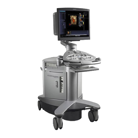
4 S y s t e m S e t u p System Review User-adjustable monitor with two forward-facing speakers User-adjustable control panel Front handle Language-specific alphanumeric keyboard Central brakes Front swivel wheels Physio panel Recordable compact disk (CD-R) drive Power ON/OFF (Standby) 10 Transducer holders... - Page 149 4 S y s t e m S e t u p 1 Transducer and gel holders 2 Transducer ports 3 Keyboard light (underneath control panel) Example of the right-front view of the ultrasound system. 4 - 5 [ 1 ] I N S T R U C T I O N S F O R U S E...
- Page 150 4 S y s t e m S e t u p 1 Input/output panel with audio and video connections 2 Left-rear panel 3 Rear swivel wheel with brake 4 AC tray panel 5 Right-rear panel with storage bin 6 AC outlets for on- board peripheral devices Example of the back view of the ultrasound system.
-
Page 151: Moving The System
4 S y s t e m S e t u p Moving the System Caution: Preparations before moving the system are important to minimize potential damage to sensitive components and to avoid safety hazards. Review the moving instructions before moving the system. Caution: Do not park, or leave unattended, on a slope. -
Page 152: Using The Rear Brakes
4 S y s t e m S e t u p To set the front brakes: Press the center section of the front bumper down firmly with your foot until the brakes lock into place. This is the lowest position for the front bumper. -
Page 153: Prior To The Move
4 S y s t e m S e t u p Prior to the Move Power OFF: Briefly press and then release the power on/off switch ( ) to power off the ultrasound system. The power on/off switch is located to the right of the CD-R drive. -
Page 154: After The Move
4 S y s t e m S e t u p After the Move Caution: Make sure the ultrasound system has proper ventilation during operation. Do not position the system against walls or hard surfaces that would impede free ventilation around the system. Caution: Do not allow linens, bedding, and/or hanging curtain partitions to block the ultrasound system's ventilation. -
Page 155: System Startup
4 S y s t e m S e t u p System Startup The first step to operating the ultrasound system is to connect the system to a power source. AC Tray Panel Identify the version of the AC tray panel on your system using the illustrations. -
Page 156: Supplying Power To The System
You can also use the green partial power on/off switch ( ) to place the system in a standby status, using the Mobile QuikStart optional feature. Siemens recommends powering off the system every 24 hours to maintain optimal performance. Note: This switch does not completely shut down or disconnect the system from the power mains. -
Page 157: Mobile Quikstart For Portable Studies (Standby)
4 S y s t e m S e t u p To power off the system: 1. Briefly press and then release the power on/off switch ( ) to power off the ultrasound system. 2. Select the Shut Down button on the displayed System Shut Down dialog box. -
Page 158: Adjusting Controls On The Monitor
4 S y s t e m S e t u p Adjusting Controls on the Monitor Contrast Control Brightness Control Monitor self test Degauss Monitor. For consistency in image reproduction, adjustments to the brightness and contrast of the viewing monitor should be made prior to adjusting the print quality of installed documentation devices. - Page 159 4 S y s t e m S e t u p lock To restore and the factory default monitor settings for brightness and contrast: 1. Simultaneously press the two Brightness buttons ( ) located on the right front underside of the monitor. The system restores the factory default setting of 32% for Brightness.
-
Page 160: Testing The Monitor
Location of monitor buttons 4-14 The green monitor LED (under the Siemens logo) blinks and the first test pattern in the sequence displays on the screen. 2. Observe the cross-hatch display and note any differences from the correct display described above. -
Page 161: Connecting And Disconnecting Transducers
4 S y s t e m S e t u p Connecting and Disconnecting Transducers Caution: Ensure that the system is in freeze before connecting and disconnecting transducers. If a transducer is disconnected before the image is frozen, the system will display an error message and it will be necessary to reset the system before continuing to use it. -
Page 162: Array Transducers
4 S y s t e m S e t u p Array Transducers Connect an array transducer to any of the three available array ports. Caution: You must freeze the system before connecting or disconnecting a transducer. Note: When transducer connectors are being attached to or disconnected from the system, resistance may be encountered due to the special shielding material inside the connectors. -
Page 163: Protective Transducer Holder
4 S y s t e m S e t u p Protective Transducer Holder Caution: Transducer holders have variable sizes, both in depth and diameter. To avoid transducer damage, you must use the holder or insert provided for transducers that have small or large diameter handles or for specialty transducers, such as endocavity transducers. -
Page 164: Transducer Cable Management
4 S y s t e m S e t u p Transducer Cable Management Use the transducer cable hooks to manage one or more transducer cables. The transducer cable hooks support your cables and protect them from contact with the floor. To install a transducer cable hook: Note: A transducer cable hook can mount on any transducer holder. -
Page 165: Connecting System Accessories
4 S y s t e m S e t u p Connecting System Accessories The ultrasound system has connections for system accessories. Front System Panel 1 PS2 Port (Barcode Connection) 2 USB-A Connection 3 Footswitch Connection 4 Headphone Connection 5 LED for Microphone 6 Microphone Connection 7 On/Off Switch... -
Page 166: Input/Output Panel Connections
EN 60601-1-1 and IEC 60601-1-1. Siemens can only guarantee the performance and safety of the devices listed in the System Reference. If in doubt, consult the Siemens service department or your local Siemens representative. -
Page 167: Connecting Peripheral Equipment
Connecting Peripheral Equipment On-board peripheral devices must be installed by an authorized Siemens representative or by a Siemens approved third party. Any use of other devices with the system will be at the user's risk and may void the system warranty. - Page 168 4 S y s t e m S e t u p 1 Patient environment represented by 4 Peripheral equipment power shading, extending exactly 5 Printer data cable 1.5 meters (1.8 meters [6 feet] in 6 Additional Protective Ground Canada and the U.S.A.) around 7 Ultrasound system power patient and ultrasound system 2 Ultrasound system...
-
Page 169: On-Board Vs. Off-Board Documentation Devices
Doing so will cause the ultrasound system to be out of Installing Off-Board compliance and may create a safety hazard. Printers Ch 5 Installing the Note: Only authorized Siemens representatives are permitted to install Off-Board Video documentation devices on-board the ultrasound system. Cassette Recorder (VCR) Ch 5 On-board documentation devices must be installed by authorized Siemens representatives. -
Page 170: System Ergonomics
4 S y s t e m S e t u p System Ergonomics You can make the following adjustments to the system: Monitor – You can tilt and swivel the monitor for optimal viewing while scanning. The sides of the monitor provide a general hand hold for tilting and swiveling the monitor. -
Page 171: Configuring The Print/Store Function
4 S y s t e m S e t u p Configuring the Print/Store Function You can designate a PRINT/STORE key for saving and/or printing, choose the output format for saved and printed images, configure additional storage, and set print options, such as print timing. Use the system presets Print/Store to set this configuration. - Page 172 4 S y s t e m S e t u p 4. Select the Configure Printers tab and enable the required Auto Transfer (print timing) option for each printer: – During Exam – system prints when film sheet is full, according to selected layout.
-
Page 173: Choosing The Output Format For Images
4 S y s t e m S e t u p Choosing the Output Format for Images Note: Use the system presets to specify the data captured for clips. Use the system presets to choose one of the following output formats for DIMAQ Protocols printed and stored images: Print/Store... -
Page 174: Selecting Image Text For Display
4 S y s t e m S e t u p Selecting Image Text for Display Use the system presets to select image text for display on images saved in the ultrasound image output format. Basic System Image text includes patient name, imaging parameter values, and scale markers. -
Page 175: Configuring Additional Storage
4 S y s t e m S e t u p Configuring Additional Storage You can configure the system to store images to other destinations in addition to the default location of the system's hard disk (Local Database). These additional destinations are listed in the Store Server column of the Print/Store Configure Store tab accessed from the Print/Store system presets menu. -
Page 176: Configuring Print Preferences
4 S y s t e m S e t u p Configuring Print Preferences Use the system presets to configure print preferences such as paper/film size, layout, and timing (print during or after the examination). Print/Store To configure print preferences: 1. -
Page 177: Configuring Printer Properties
4 S y s t e m S e t u p Configuring Printer Properties You can configure printer properties such as color management for printers that have Windows printer drivers and that are connected to the ultrasound system. Use the system presets to configure printer properties. Printer properties are configured through the Windows Properties dialog box Service for the printer. -
Page 178: Optimizing The Sony Up-D23 Md Printer Configuration
2. Select the Paper tab and then select the High Speed check box. 3. Select the Graphics tab. 4. Select Color Balance from the Color Adjust drop-down box at the top of the tab and enter the following values recommended by Siemens: Value Recommended for Field for the Color Balance selection High Speed Printing Cyan –... - Page 179 2. Select the Paper tab and then clear the High Speed check box. 3. Select the Graphics tab. 4. Select Color Balance from the Color Adjust drop-down box at the top of the tab and enter the following values recommended by Siemens: Value Recommended for Field for the Color Balance selection High Quality Printing Cyan –...
- Page 180 4 S y s t e m S e t u p 4 - 3 6 [ 1 ] I N S T R U C T I O N S F O R U S E...
- Page 181 5 Beginning an Examination Patient Registration ................... 3 Registering or Pre-registering a Patient ............3 Selecting a Scheduled Procedure for Registration......... 6 Fields in the Patient Registration Form............7 Patient Data.................... 7 History (OB or GYN Study) ..............8 Institution ....................9 Exam ......................
- Page 182 5 B e g i n n i n g a n E x a m i n a t i o n 5 - 2 [ 1 ] I N S T R U C T I O N S F O R U S E...
-
Page 183: Patient Registration
5 B e g i n n i n g a n E x a m i n a t i o n Patient Registration Use the Patient Registration form to search for previously entered registration data, register a patient for immediate examination, or pre-register a patient for a later examination. - Page 184 5 B e g i n n i n g a n E x a m i n a t i o n 3. To retrieve patient data previously entered (for a previous patient or a pre-registered patient): Note: Use an asterisk (*) to indicate partially known values. For example, to search for the last name "Miller,"...
- Page 185 5 B e g i n n i n g a n E x a m i n a t i o n 8. To store the entered registration data as an image and then begin the examination using the entered registration data, press a PRINT/STORE key located on the control panel that is assigned the store function.
-
Page 186: Selecting A Scheduled Procedure For Registration
Note: For scheduled procedures to be available, the ultrasound system must be [2] Instructions for Use connected to a HIS/RIS (Worklist) server configured for MPPS (Modality Performed PATIENT DATA: Procedure Step). Consult the Siemens service department or your local Siemens Procedures and representative for assistance. procedure steps... -
Page 187: Fields In The Patient Registration Form
5 B e g i n n i n g a n E x a m i n a t i o n Fields in the Patient Registration Form The Patient Registration form includes the following sections: PATIENT, INSTITUTION, EXAM, and HISTORY. Use the system presets to select the required date format and to create entries for the INSTITUTION section. -
Page 188: History (Ob Or Gyn Study)
5 B e g i n n i n g a n E x a m i n a t i o n History (OB or GYN Study) [2] Instructions for Use CALCS: Growth Curves Graph Ch 3 History In this field: Enter... -
Page 189: Institution
5 B e g i n n i n g a n E x a m i n a t i o n Institution Note: When you enter a new value into an INSTITUTION field (assuming that the maximum number of entries for that field has not been reached), the system automatically adds the entered value as a new entry to the registration configuration list in Basic System the system presets. -
Page 190: During The Examination
5 B e g i n n i n g a n E x a m i n a t i o n During the Examination During an examination, you can correct registration data, begin a new study, select a different transducer or imaging mode, optimize the image, print and store images, activate the measurement function, and view the patient report. -
Page 191: Study Type Selection
5 B e g i n n i n g a n E x a m i n a t i o n Study Type Selection The system lists study type abbreviations in the Patient Registration form. [1] Instructions for Use The study type you select determines the exam type used during the Study Type examination. -
Page 192: Selecting An Imaging Mode
5 B e g i n n i n g a n E x a m i n a t i o n Selecting an Imaging Mode When the system is powered on, it automatically displays in 2D-mode. You can change imaging modes by pressing the mode controls located on the control panel. -
Page 193: Printing And Storing Images
5 B e g i n n i n g a n E x a m i n a t i o n Printing and Storing Images You can print and store images during an examination (active study). Use the system presets to assign print and/or store functionality to each PRINT/STORE key. -
Page 194: Storing Clips
5 B e g i n n i n g a n E x a m i n a t i o n Storing Clips Note: Clips cannot be stored from the Review task card. Clips cannot be stored from the Compose task card during 3-Scape Imaging, unless the volume is being automatically rotated. -
Page 195: Viewing Clips
5 B e g i n n i n g a n E x a m i n a t i o n Viewing Clips You can view (play back) a clip. Review A clip graphic is displayed on each clip in the task card (for display formats other than full-screen). -
Page 196: Activating The Measurement Function
5 B e g i n n i n g a n E x a m i n a t i o n Activating the Measurement Function Measurements can be performed on real-time or frozen images. To activate the measurement function, select the Calcs task card at the bottom of the screen. -
Page 197: Printing And Storing The Patient Report
5 B e g i n n i n g a n E x a m i n a t i o n Printing and Storing the Patient Report Patient reports are stored as images (screenshots). You can print either the displayed portion or all portions of the patient report. -
Page 198: Controlling The Vcr From The Ultrasound System
5 B e g i n n i n g a n E x a m i n a t i o n Controlling the VCR from the Ultrasound System Use the selections in the VCR group box to control the VCR directly from [2] Instructions for Use the Image task card. -
Page 199: Examination Completion
5 B e g i n n i n g a n E x a m i n a t i o n Examination Completion You can end an examination (study) from the Review task card or the Patient Registration screen. To end the current examination (study): Select the Review task card tab and then select the End Exam button on the lower left of the screen;... - Page 200 5 B e g i n n i n g a n E x a m i n a t i o n 5 - 2 0 [ 1 ] I N S T R U C T I O N S F O R U S E...
- Page 201 6 Technical Description Standard Features ....................3 Operator Control Panel .................. 3 System Operating Software ................3 Processing Power..................3 15-inch (38 cm), High Resolution Color Monitor ..........4 Mobility......................4 Transducer Technology ................. 4 User-Accessible Connections ................ 4 Operating Modes ..................5 Single Modes ..................
- Page 202 6 T e c h n i c a l D e s c r i p t i o n Standard Mainframe Package ................. 14 Options......................14 Measurements and Reports ................15 General Functions..................15 General 2D-mode Measurements ............15 General M-mode Measurements ............
-
Page 203: Standard Features
6 T e c h n i c a l D e s c r i p t i o n Standard Features Note: Refer to the Accessories and Options chapter of the System Reference for a list of System Reference system-specific features and options, including transducers. -
Page 204: 15-Inch (38 Cm), High Resolution Color Monitor
6 T e c h n i c a l D e s c r i p t i o n 15-inch (38 cm), High Resolution Color Monitor 75 Hz display (PAL), 60 Hz display (NTSC) Tilt of 10° up and 8.5° down Swivel of 180°... -
Page 205: Operating Modes
6 T e c h n i c a l D e s c r i p t i o n Operating Modes Single Modes 2D-mode M-mode Color Power Pulsed Doppler Mixed Modes 2D/M-mode 2D/Doppler 2D-mode with color 2D-mode with power 2D/M-mode with color 2D/M-mode with power 2D/Doppler with color... -
Page 206: Pulsed Wave Doppler Features
6 T e c h n i c a l D e s c r i p t i o n Pulsed Wave Doppler Features Doppler measurements and calculations available for all linear, curved, [1] Instructions for Use and phased array transducers Post-Processing Fast Fourier Transformation (FFT) processing of 32 to 256 points FFT speed up to 1,920 FFTs per second at the highest sweep speed... -
Page 207: Color Doppler Features
6 T e c h n i c a l D e s c r i p t i o n Color Doppler Features 2D/Color display [1] Instructions for Use User-adjustable color region of interest (ROI), size, and position Post-Processing Independent controls for color gain, PRF, invert, baseline, resolution/frame rate, persistence, priority, and smoothing Up to four user-selectable transmit frequencies... -
Page 208: M-Mode Features
6 T e c h n i c a l D e s c r i p t i o n M-Mode Features Independent controls for M-mode gain, gate position, gate size, and [1] Instructions for Use sweep speed Post-Processing Dynamic range display from 30 dB to 70 dB in five-decibel increments M-mode gain from –20 dB to 60 dB in one-decibel increments M-mode zoom feature... -
Page 209: Post-Processing Features In Freeze Frame Or Cine
6 T e c h n i c a l D e s c r i p t i o n Post-Processing Features in Freeze Frame or CINE 2D-mode Zoom/pan – Dynamic range – Gray map – – 2D-mode tint map –... -
Page 210: Optional Features
6 T e c h n i c a l D e s c r i p t i o n Optional Features Note: Refer to the Accessories and Options chapter of the System Reference for a list of System Reference system-specific features and options, including transducers. -
Page 211: Siescape Panoramic Imaging
6 T e c h n i c a l D e s c r i p t i o n SieScape Panoramic Imaging (Optional) Available on all imaging transducers without any additional attachments SieScape images may be created up to 60 cm in length and up to 360° when the depth is less than the radius of the target area being scanned CINE display of frame by frame review capability of individual data frames within the SieScape image... -
Page 212: Teq Technology
6 T e c h n i c a l D e s c r i p t i o n TEQ Technology (Optional) Available on all imaging transducers without any additional attachments The TEQ technology (Tissue Equalization) optional feature automatically optimizes the overall field of view (FOV) image brightness uniformity by changing the DGC, overall gain, and lateral gain. -
Page 213: Cadence Contrast Agent Imaging
6 T e c h n i c a l D e s c r i p t i o n Cadence Contrast Agent Imaging (Optional) Available for the following transducers and study types/exam types: Transducer Imaging Techniques Study Types/Exam Types C5-2 ECI, AEI All except Fetal Echo and Obstetrics... -
Page 214: Standard Mainframe Package
6 T e c h n i c a l D e s c r i p t i o n Standard Mainframe Package Note: Refer to the Accessories and Options chapter of the System Reference for a list of System Reference system-specific features and options, including transducers. -
Page 215: Measurements And Reports
6 T e c h n i c a l D e s c r i p t i o n Measurements and Reports Measurements are available during all examinations on real-time, frozen, and CINE images. All applications support annotations, pictograms, measurement tools, reports, and system presets. -
Page 216: Application-Specific Measurements
6 T e c h n i c a l D e s c r i p t i o n Application-specific Measurements The following application-specific measurements are available when using the ultrasound system: Abdominal All general measurements Measurement labels for Abdominal, Renal, and Pelvic exams Small Parts All general measurements Measurement labels for Breast, Thyroid, Testis, Digital, Musculoskeletal,... -
Page 217: Obstetrics (Ob)
6 T e c h n i c a l D e s c r i p t i o n Obstetrics (OB) All general measurements and calculations Calculations for gestational age (GA), Composite GA, estimated fetal weight (EFW), OB ratio, cephalic index (CI), fetal age and estimated date of confinement (EDC), micturated volume Circumference measurement customization for ellipse and 2D-mode trace... -
Page 218: Pediatric
6 T e c h n i c a l D e s c r i p t i o n Pediatric Neonatal Head unlabeled measurements Hip Angle 2D-mode measurement labels for left and right hip, and a Graf sonometer for each side The patient report includes hip descriptions. -
Page 219: Measurement Range And Accuracy
6 T e c h n i c a l D e s c r i p t i o n Measurement Range and Accuracy The following tables describe the variability in accuracy for clinical measurements. Clinical Measurements: Range and Accuracy Direct Tolerance Measurement... - Page 220 6 T e c h n i c a l D e s c r i p t i o n 2D-Mode Measurements 2D-mode Measurements Range or Formula Minimum Value Maximum Value Distance 0-34 cm D-Tol(D) D + Tol(D) Distance Ratio D1/D2 (D1-Tol(D1))/(D2+Tol(D2)) (D1+Tol(D1))/(D2-Tol(D2))
- Page 221 6 T e c h n i c a l D e s c r i p t i o n Doppler Measurements Doppler Measurements Range or Formula Minimum Value Maximum Value Velocity 20 – 600 cm/sec V-Tol(V) V+Tol(V) Frequency Vcosθ/1540 cosθ(V-Tol(V))/1540 cosθ(V+Tol(V))/1540...
-
Page 222: Mode Measurements
6 T e c h n i c a l D e s c r i p t i o n M-Mode Measurements M-Mode Measurements Range for Formula Minimum Value Maximum Value Distance 0 – 24 cm D-Tol(D) D+Tol(D) Time @ 0 –... -
Page 223: Image Display
6 T e c h n i c a l D e s c r i p t i o n Image Display TV Standards EIA/NTSC and CCIR/PAL Monitor Color 15 inch (38 cm) Gray Scale 256 levels Color 256 shades Image polarity Positive (black on white) or negative (white on black) Date/Time display... - Page 224 6 T e c h n i c a l D e s c r i p t i o n Image Screen Display Arranged by Image, Calcs, Review, and Compose task cards Additional screens to support filming (printing), reports, patient browser, system presets, online help, and the patient registration form Recordable image area of 800 by 600 pixels Centimeter (cm) scale marker with depth of display, focal zones: number and...
-
Page 225: System Requirements
EN 60601-1-1 and IEC 60601-1-1. Siemens can only guarantee the performance and safety of the devices listed in the Accessories and Options chapter. If in doubt, consult the Siemens service department or your local Siemens representative. -
Page 226: Leakage Currents
6 T e c h n i c a l D e s c r i p t i o n Leakage Currents Connecting peripheral products and accessories from non-isolated sources may result in chassis leakage current exceeding safe levels. Audio, Video, and Data Transmission Connections Input and Output Signals Signal... -
Page 227: Environmental Requirements
6 T e c h n i c a l D e s c r i p t i o n Environmental Requirements EMC Note: Operating the Antares ultrasound imaging system in close proximity to sources of strong electromagnetic fields, such as radio transmitter stations or similar installations may lead to interference visible on the monitor screen. -
Page 228: System Classifications
6 T e c h n i c a l D e s c r i p t i o n System Classifications The Antares ultrasound imaging system has the following classifications: Type of protection against electrical shock: Class I Degree of protection against electrical shock: Type B equipment Type BF for ECG connection... -
Page 229: Standards Compliance
This product is provided with a CE marking in accordance with the regulations stated in Council Directive 93/42/EEC of June 14, 1993 concerning Medical Devices. Siemens Medical Solutions USA, Inc., is certified by Notified Body 0123 to Annex II.3 – Full Quality System. - Page 230 6 T e c h n i c a l D e s c r i p t i o n 6 - 3 0 [ 1 ] I N S T R U C T I O N S F O R U S E...
Need help?
Do you have a question about the ACUSON Antares and is the answer not in the manual?
Questions and answers