Table of Contents
Advertisement
Quick Links
Installation and Operating Instructions
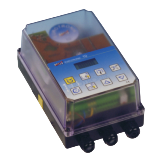
The electronic backwash controller EUROTRONIK-20 switches the filtration pump of a swimming-pool on
and off at programmable times and controls the backwashing and clear rinsing cycles for cleaning the
filter. The EUROTRONIK, which is mounted on the 6-way valve with a protected quick coupling,
automatically moves the valve into the correct position and operates the filter pump. The time of the
backwashing and clear rinsing cycles is adjustable and can be seen in the LCD display.
The backwashing cycle can be carried out both on a time-control (by way of the integrated digital switch
clock) as well as pressure-dependent basis. The adjustable pressure switch (art. no. 2000599015) is not
included in the delivery package. It is also possible to start the backwashing cycle manually with a key in
the housing cover.
A connection for a 230 V motor-operated valve enables withdrawal of the water needed for the
backwashing cycle directly from the swimming pool instead of from the overflow collecting tank and
replenishment of fresh water during backwashing. An additional floating relay contact can be used
during backwashing to operate a second pump (backwash pump or blower).
A connection for an external temperature regulator provides the possibility of heating the pool during the
filtration times. An internal latch makes sure that the heater will only be enabled when the pump is running.
To empty the swimming pool, the 6-way valve can be moved into the position Empty. The key for this is
also located in the housing cover. For maintenance purposes the valve can also be moved into the
position Closed with a further key.
The respective valve position and position changes can be read on an LCD display in the housing cover
without having to open the housing. The valve disk is lifted before turning to protect the star seal. The
pump is switched off during this time.
Dimensions:
Power supply:
Power consumption of the controler:
Breaking capacity:
Motor-operated valve:
System of protection:
Ambient conditions:
Usable valves:
With appropriate adapter
Static water pressure:
Water column above the valve:
The specified valve variants are guide values. Since the design and geometry of the valves can change
and these sometimes show significant sample variations, compatibility with the EUROTRONIK may need
to be requested from the valve manufacturer.
Art.No. 3104811211
Function
Technical specifications
0-40°C, max. 95% r.H. non condensing
R
-20
245mm x 140mm x 95mm
230V/50Hz
approx.10VA
max. 1,1 kW (AC3)
230V
IP 54
Praher 1½" and 2"
Speck 1½" and 2"
Midas 1½" and 2"
Astral 1½"
Astral 2"
Hayward 1½"
max.0,3bar
max. 3,0m
Advertisement
Table of Contents

Related Manuals for OSF EUROTRONIK-20

Summary of Contents for OSF EUROTRONIK-20
-
Page 1: Function
Art.No. 3104811211 Function The electronic backwash controller EUROTRONIK-20 switches the filtration pump of a swimming-pool on and off at programmable times and controls the backwashing and clear rinsing cycles for cleaning the filter. The EUROTRONIK, which is mounted on the 6-way valve with a protected quick coupling, automatically moves the valve into the correct position and operates the filter pump. -
Page 2: Table Of Contents
Operating instructions EUROTRONIK-20 Page: 2 Table of contents Seiten Function Technical specifications Mounting Preparation of the 6-way valve Preparation of the controller Mounting on an Astral 2" valve Mounting on Astral, Midas and Hayward valves Mounting of the EUROTRONIK Electrical connection... -
Page 3: Mounting
Then insert the shorter osf pin delivered with the device in the middle of the hole in the valve shaft. If the pin is too loose in the hole, it can be fastened with a little adhesive or grease to facilitate mounting of the controller. -
Page 4: Mounting On An Astral 2" Valve
The slides must then catch in the guide grooves of the valve when released. The valve shaft may not be turned with the device when clipping on the controller. The osf pin in the valve shaft must now be caught in the slot of the coupling. -
Page 5: Electrical Connection
The osf pressure switch (art. no. 2000599015) can be connected to the terminals 10 and 11. It is screwed into the manometer connection in the 6-way valve. The metal body of the pressure switch must be grounded. -
Page 6: Operating Elements
Operating instructions EUROTRONIK-20 Page: 6 Operating elements LCD display Program timer Manual control of pump (Filtration times) Close valve Controller ON/OFF Backwash (manual) Empty swimming pool Set time Program timer Change values (Backwash and clear rinsing times) LCD display Normal operating display during filter time showing the current time and valve position. -
Page 7: Switching The Controller On/Off
Operating instructions EUROTRONIK-20 Page: 7 The valve disk is turned into the position Empty. Rotate Empty The valve disk is lowered into the position Empty. Lower Empty The valve is in the position Empty. The filter pump is on. Pump on Empty The valve disk is lifted to be turned into the position Closed. -
Page 8: Programming The Timer (Backwashing And Clear Rinsing Times)
Operating instructions EUROTRONIK-20 Page: 8 Programming the timer (backwashing and clear rinsing times) The integrated weekly timer for automatic backwashing and clear rinsing is programmed with the key Duration Back: 1. Press the key appears in the display. 2. The desired duration of backwashing (in seconds) can then be set with the keys . -
Page 9: Backwashing (Manual)
Operating instructions EUROTRONIK-20 Page: 9 Wed 7:30 display -------- 2. Set the filtration time on with the keys (between Sun. 23:59 and Mon. 0:00). 3. To delete the switch time, press the key again. Backwashing (manual) A backwashing cycle can be started manually at any time – irrespective of how the timer has been programmed –... -
Page 10: Dip Switch On The Upper Circuit Board
Operating instructions EUROTRONIK-20 Page: 10 DIP switch on the upper circuit board Intermittent backwashing and fortnightly backwashing can be activated with a DIP switch on the upper circuit board inside the EUROTRONIK. The housing has to be opened to access these operating elements. -
Page 11: Service Terminal (Only For Service Personnel)
Operating instructions EUROTRONIK-20 Page: 11 Service terminal (only for service personnel) An osf service terminal (art. no. 3010000900) can be connected to this controller for optimum adjustment of the controller to the different types of swimming pool and to facilitate commissioning and fault diagnosis. -
Page 12: Filter Pump
Operating instructions EUROTRONIK-20 Page: 12 1. The following display appears after pressing the key Heater: Manual control of contact betw. terminals 3+5. 2. The heater can be enabled with the key (K3 closed) and disabled again with the key (K3 open). -
Page 13: Servomotor
Operating instructions EUROTRONIK-20 Page: 13 Servomotor This line shows whether the servomotor in the EUROTRONIK to turn the 6-way valve is on or off. The following displays are possible: Act.motor: OFF The servomotor is off. Act.motor: UP The servomotor lifts the valve disk or turns it into the next position.
Need help?
Do you have a question about the EUROTRONIK-20 and is the answer not in the manual?
Questions and answers