LG DLEX4370 Series Service Manual
Electric & gas dryer
Hide thumbs
Also See for DLEX4370 Series:
- Owner's manual (46 pages) ,
- Owner's manual (100 pages) ,
- Owner's manual (48 pages)
Advertisement
Quick Links
CONFIDENTIAL
MODEL :
Electric
Gas
DLEX4370*
DLGX4371*
Any reproduction, duplication, distribution (including by way of email, facsimile or other electronic means),
publication, modification, copying or transmission of this Service Manual is STRICTLY PROHIBITED unless
you have obtained the prior written consent of the LG Electronics entity from which you received this Service
Manual. The material covered by this prohibition includes, without limitation, any text, graphics or logos in this
Service Manual.
Copyright ©
2016 - 2017
LG Electronics Inc. All rights reserved. Only training and service purposes.
1
Advertisement

Related Manuals for LG DLEX4370 Series


Summary of Contents for LG DLEX4370 Series
- Page 1 Service Manual is STRICTLY PROHIBITED unless you have obtained the prior written consent of the LG Electronics entity from which you received this Service Manual. The material covered by this prohibition includes, without limitation, any text, graphics or logos in this Service Manual.
- Page 3 13-2-2. CABINET AND DOOR ASSEMBLY: GAS TYPE ............58 13-3-1. DRUM AND MOTOR ASSEMBLY: ELECTRIC TYPE ..........59 13-3-2. DRUM AND MOTOR ASSEMBLY: GAS TYPE ............60 Copyright © 2016 - 2017 LG Electronics Inc. All rights reserved. Only training and service purposes.
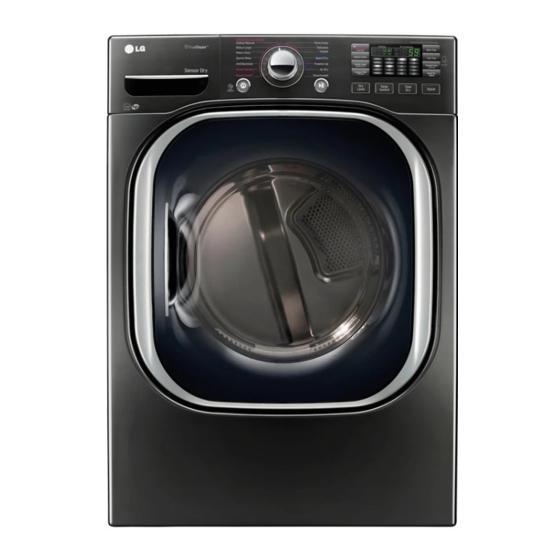
- Page 4 ■ Name : Electric and Gas Dryer ■ Power supply : Refer to the rating label on the dryer. : 120 VAC Electric: 240VAC ■ Size : 27 X 30 X 38 11/16 (inch) ■ Dryer capacity : Normal Cycle IEC 7.4 cu.ft. (225 lb/10.2 kg) Steam Cycle IEC 7.4 cu.ft.
- Page 5 DLEX4370* DLGX4371* Blue White / Stainless Silver / Black STS Powder coating Chrome 120 V/ 60 Hz (11.5 A) 1.12W(0.08A) 7.4cu.ft 140.2 / 138.2 High / Low / Off Stainless 27 X 30 X 38 11/16 (inch) 29 1/2 X 30 3/4 X 44 3/4 (inch)
- Page 6 FEATURES AND BENEFITS INSTALLATION INSTRUCTIONS Dryer Rack Installation Instructions Open the door. Put the dryer rack into Check and be sure that the Hold the dryer rack the drum front of the rack is properly with both hands. seated behind the lint filter.
- Page 7 3-1. Connecting Electric Dryers 4-wire direct If this type is available at your home. you will be connecting to a fused disconnect or circuit breaker 3-wire direct 5" (12.7 cm) If this type is available at your home. you will be connecting to a fused disconnect or circuit breaker...
- Page 9 3-2 Connecting the gas supply...
- Page 10 Connect Inlet Hose 21.8 150~800...
- Page 12 Auto reset -31°F (-35°C) Same shape as outlet thermostat. 4. LED Lamp Schematic: If the lamp is turned on It is not by connecting is normal. measured by multimeter because V is 3.2V Measure resistance of the following terminal 1) Door open Terminal: COM - NC (1-3) Terminal: COM - NO (1-2) 2) Door closed...
- Page 14 Ω Ω Electric type 15. Inlet. valve Measure resistance of the Following terminal Left picture -.plate...
- Page 15 When checking Component, be sure to turn Power off, then do voltage discharge sufficiently. Ω Ω Ω Ω...
- Page 16 Heater Relay(Black) Heater Relay(Blue) AG Heater Relay(White)
- Page 17 Heater Relay(Black) Heater Relay(Blue)
- Page 18 TEMP. FABRIC MAXIMUM STEAM DEFAULT TIME FABRIC TYPE CONTROL LEVEL STATE AMOUNT Comforter Single (1 each) STEAM Bedding STEAM SANITARY™ SANITARY™ (39 minutes) Children's clothing 3 lbs. comforter Single (1 each) STEAM FRESH™ (20 minutes) Shirts* 5 each STEAM FREASH™ 8 lbs.
- Page 20 • MORE TIME pressed. • Pressing the MORE TIME button adjusts the The display shows: load size from 1to 5 articles or a big load indicated by in the display. Thermistor of blower 1 error is displayed in the Outlet thermistor open or shorted. housing drying cycle or test mode.
- Page 21 Symptom Check Point 1. Not heating 1.Check Electric Wiring. 2.Check the motor operation. 3.Voltage of the Main PWB. 4. Check Heater element’s Resistance. <Electric Dryer>...
- Page 22 <Electric Dryer> Table 1. Resistance for Thermistor Temperature.
- Page 23 Not heating (Electric) Unplug UNIT / Check heater Check lint Filter One or both elements. Heater elements Terminal: 1(COM) – 2 = 10Ω Clean if needed. defective. Explain to owner responsibility Terminal: 1(COM) – 3 = 10Ω Terminal: 2 – 3 = 20Ω formance and safety reason.
- Page 24 <Gas Dryer>...
- Page 25 <Gas Dryer> Table 1. Resistance for Thermistor Temperature.
- Page 26 Not heating (Gas) Unplug UNIT / Check gas valve Defective gas valve Check lint Filter Valve1 terminal > 1.5kΩ~2.5kΩ Clean if needed. Valve2 terminal > Explain to owner responsibility to 1.5kΩ~2.5kΩ and safety reason. Unplug UNIT / Check Igniter Defective Igniter Resistance value = 50~800Ω...
- Page 27 Symptom Check Point 2. Not tumbling 1.Check Electric Wiring. 2.Check the Door properly closed. 3.Voltage of the Main PWB. 4. Check Blower thermostat’s Resistance <Electric / Gas Dryer>...
- Page 28 How does the Flow sense function display the clogging of duct ? The FlowSense display consists of four bars inside a box. The display has only two possible displays as only two possible displays as shown here (Also see the figure shown below): No bars displayed.
- Page 29 Once you have completed the installation of the dryer, During the two minute test cycle, monitor the FLOW use this test to make sure the condition of the exhaust SENSE display on the control panel. If the Flow system is adequate for proper operation of the dryer. Sense indicator text lights up, the exhaust system This test should be performed to alert you to any serious is restricted.
- Page 30 dryin...
- Page 32 120V AC Electrical Supply...
- Page 33 ✽...
- Page 34 Connection of Tap Relay with PCB ASSEMBLY (Gas) Remark Color Harness Blue Wire Check the matching color between harness wire and tap relay. Black Connector Housing (Black housing – black tap relay) Black Wire Tap Relay 1 Connector Housing ✽...
- Page 35 Thermistor Test --- Measur e with Power Off...
- Page 36 Motor Test Drum does not rotate, fan does not turn, heater does not function. Ω Ω Ω Ω page 12 Ω page 15...
- Page 37 PCB.
- Page 38 PCB.
- Page 39 element.
- Page 40 GAS Valve Test - Gas Type GAS V alve test - Gas T ype Ω...
- Page 41 DC pum...
- Page 42 CHANGE GAS SETTING (NATURAL GAS, PROPANE GAS) Changing orifices and gas valve adjustments improperly can result in an Warning explosion and/or fire. Conversion must be made by a qualified technician. Initially, The burner is set for natural gas at the factory. The propane orifice conversion kit is sold as a service part to authorized servicers only.
- Page 44 Unplug the dryer before servicing. WARNING ! TOP PLATE When you disassemble the top plate, be sure to disconnect the dryer from its electrical supply. Protect your hands and arms from sharp edges when working. To reduce the risk of injury to persons adhere to all industry recommended safety procedures including the use of long sleeved gloves and safety glasses.
- Page 45 WARNING ! CONTROL PANEL ASSEMBLY When you disassemble the control panel, be sure to disconnect the dryer from its electrical supply. Protect your hands and arms from sharp edges when working. To reduce the risk of Injury to persons adhere to all industry recommended safety procedures including the use of long sleeved gloves and safety glasses.
- Page 46 COVER CABINET WARNING ! When you disassemble the door switch connector, be sure to disconnect the dryer from its electrical supply. Protect your hands and arms from sharp edges when working. To reduce the risk of Injury to persons adhere to all industry recommended safety procedures including the use of long sleeved gloves and safety glasses.
- Page 47 WARNING ! TUB DRUM FRONT When you disassemble the lamp connector, be sure to disconnect the dryer from its electrical supply. Protect your hands and arms from sharp edges when working. To reduce the risk of Injury to persons adhere to all industry recommended safety procedures including the use of long sleeved gloves and safety glasses.
- Page 48 WARNING ! DRYER EXHAUST CHANGE Before performing this exhaust installation, be sure to disconnect the dryer from its electrical supply. Protect your hands and arms from sharp edges when working inside the cabinet. To reduce the risk of Injury to persons adhere to all industry recommended safety procedures including the use of long sleeved gloves and safety glasses.
- Page 49 AIR DUCT & FILTER ASSEMBLY Disassemble the top plate. Remove the cover cabinet. Remove the filter. Remove the cover guide. Remove 2 screws. Remove the air duct. Remove the filter. Remove 3 screws. Remove the cover grid. Disconnect the electrode sensor.
- Page 50 BLOWER HOUSING Remove the top plate. Remove the cabinet cover and front bulkhead. Remove the drum assembly. Remove 2 screws and cover (air guide). Remove the bolt and washer. Remove the blower wheel. (Left-hand thread). Disconnect the motor clamp and motor. BACK COVER Open the top plate.
- Page 51 Replacing the Inlet Hose 1. Press and hold the release ring to remove the hose from the nozzle. 2. Remove the 7 screws from the rear cover. 3. Lift the rear tub off the support and pull it out. 4. Replace the hose, and assemble the cable tie holder in the rear tub.
- Page 52 5. Remove the hose in generator. 6. Remove the cable tie holder in the rear tub. 7. Replace the hose, and assemble the cable tie holder in the rear tub. 8. After connection the hose to the generator, install the clamp.
- Page 53 1. Remove the six connectors from the generator. 2. Remove the thermistor screw from the generator. 3. Remove the steam harness cable tie holder in the rear tub. 4. Replace the steam harness and assemble the cable tie holder in the rear tub. 5.
- Page 54 1. Remove the cover and screws. 2. To remove the rear tub, take off the steam 3. Remove the bracket from the generator first. Then remove the rear tub. steam generator. 4. Reassemble the steam generator and bracket. 5. Assemble the cover and screws.
- Page 55 13-1. Control Panel and Plate Assembly A213 A211 A210 A140...
- Page 56 13-2-1. Cabinet and Door Assembly: Electric Type A590 A700 A800 A570 A390 A560 A130 A131 A330 A600 A300 A305 A330 K730 A308 A325 A325 A500 A320 A320 A300 A300 A530 A310 A310 A520 A525 A495 A410 A540 A430 A308 A400 A420 A450 A460...
- Page 57 13-2-2. Cabinet and Door Assembly: Gas type A590 A700 A800 A390 A130 A131 A600 A300 A330 K730 A308 A550 A325 A500 A320 A300 A530 A310 A520 A525 A495 A540 A410 A430 A400 A420 A450 A460...
- Page 58 13-3-1. Drum and Motor Assembly: Electric Type K740 K742 K400 K120 F200 K743 K509 K502 K507 K505 K741 K410 K140 K100 K720 K411 K130 K250 K251 K310 K320 K330 K221 K340 K230 K620 K210 K250 K360 K350 K610 K560 K550 K251 K336 K335...
- Page 59 13-3-2. Drum and Motor Assembly: Gas type K400 F200 K507 K740 K509 K502 K742 K505 K120 K743 K410 K741 K140 K720 K411 K100 K130 K250 K251 K320 K310 K330 K335 K221 K340 K230 K620 K336 K210 K250 K360 K350 K610 K560 K550 K251...
- Page 60 FOR LG TECHNICIAN MAR. 2017 PRINTED IN KOREA MFL69290405...
Need help?
Do you have a question about the DLEX4370 Series and is the answer not in the manual?
Questions and answers