Table of Contents
Advertisement
Quick Links
Advertisement
Table of Contents

Subscribe to Our Youtube Channel
Related Manuals for Prostat PDT-740B

Summary of Contents for Prostat PDT-740B
- Page 1 User Manual...
-
Page 3: Table Of Contents
Suggestion “A” for Material Static Decay Measurements General Specifications © 2011 by Prostat® Corporation. All rights reserved. Printed in the United States of America. No part of this manual may be used or reproduced in any manner whatsoever without written permission. For information contact Prostat Corporation, 1072 Tower Lane, Bensenville, IL 60106 USA Prostat is the registered trademark of Prostat®... -
Page 4: Introduction
ESD control products. The PDT-740B Static Decay Timer is used with Prostat’s precision portable Charge Plate Monitor kit com- ponents, including the PFM-711A Field Meter, CPM-720A Charge Plate Assembly and PCS-730 ±1kV Charg- ing Source. -
Page 5: Function
The PDT-740B is designed specifically to measure decay time of ionizers and materials in seconds and tenths of a second from 1,000 to 100, 50 or 10 volts. It is used with the Prostat PFM-711A Field Meter and CPM-720 Charge Plate Monitor Assembly, or an equivalent instrument having an analog output of 1 volt equaling 10,000 electrostatic volts. -
Page 6: Connecting The Pdt-740B To Pfm-711A Fieldmeter
1. Insert one cable mini-phono plug into the PFM-711A Analog Output receptacle located on the left front panel of the instrument. 2. Insert the opposite end of the cable into the PDT-740B Analog Input receptacle located on the left front panel of the instrument. -
Page 7: Normal Operation For Ionization Static Decay Measurements
The dual phono plug cable assembly is connected to the analog output of the PFM-711A Field Meter and the Analog Input of the PDT-740B Decay Timer. With the Charge Plate Assembly (CPM) installed on the Field Meter, the Charging Source is used to apply greater than ±1,000 volts to the CPM. To measure an ionizers decay time performance, proceed as follows: A. - Page 8 1. The Green LED Decay Cycle Ready automatically goes OFF 2. The PDT-740B LCD display begins timing function in seconds 3. The PDT-740B Red LED Timing in Progress automatically comes ON and stays ON until voltage decays to 100 (±2) volts 4.
-
Page 9: Suggestion "A" For Material Static Decay Measurements
The dual phono plug (input) cable assembly is connected to the analog output of the PFM-711A Field Me- ter and the Analog Input of the PDT-740B Decay Timer. The Charge Plate Assembly (CPM-720) is installed on the Field Meter. One end of a high resistance lead is connected to the CPM-720 Plate and the other end connected to a Prostat PGB-745 Electrode. - Page 10 PDT-740B Static Decay Timer A. Setup PFM-711A Field Meter, PCS-720 Charge Plate and PDT-740B Static Decay Timer as described and illustrated above. B. Place the material to be tested on a grounded steel test bed. C. Connect the PGB-745 Static Decay Electrode to the CPM-720 Charge Plate using a high resistance lead, and suspend the electrode above the specimen to be tested.
- Page 11 1. The Green LED Decay Cycle Ready automatically goes OFF 2. The PDT-740B LCD display begins timing function in seconds 3. The PDT-740B Red LED Timing in Progress automatically comes ON and stays ON until voltage decays to set cutoff (±2) volts 4.
- Page 12 PDT-740B Static Decay Timer 1. Place the specimen to be tested on an insulated test bed 2. Place the second electrode on the test specimen and attached to ground. 3. The first electrode is connected and used as described above.
-
Page 13: General Specifications
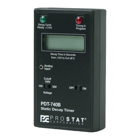
PDT-740B Static Decay Timer PdT-740b Static decay Timer Specifications Controls: OFF-ON Cut Off Voltage, 10, 50 and 100 Volts (Selects Voltage to stop timing) Indicators: Green LED: Decay Cycle Ready > ±1kV, CPM voltage > ±1,000 volts Red LED: Timing in Progress, CPM voltage decay timing activated LOBAT displayed when battery voltage <6.0 volts... - Page 14 PDT-740B Static Decay Timer NOTeS Rev. B / February 2005...
- Page 16 Specifications are subject to change without notice. All Prostat trademarks and trade names are the property of Prostat Corporation. All other trademarks and trade names are the property of their respective companies. P R O F E S S I O N A L...
Need help?
Do you have a question about the PDT-740B and is the answer not in the manual?
Questions and answers