
Related Manuals for Morehouse C705P


Summary of Contents for Morehouse C705P
- Page 1 C705P Digital Indicator Meter Instruction Manual 10/20/2022 Rev: 1 Instruction Manual PM-5947 Copyright © 2022...
-
Page 2: Table Of Contents
Table of Contents DISPLAY & KEYPAD DETAILS ..................2 INSTALLATION & OVERVIEW ..................4 Installation of C705P force data instrument ............4 Power Connections (AC version) ................5 USB Port ....................... 5 Getting Started ...................... 5 SYSTEM CONFIGURATION .................... 6 1.1 Configuration Menus .................. -
Page 3: Display & Keypad Details
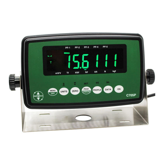
DISPLAY & KEYPAD DETAILS This instrument utilizes a 7-digit LCD (Liquid Crystal Display) with adjustable LED backlight. The Table below summarizes the display annunciators: Symbol Display Indication ➔0 Indicates that the instrument is in Tare mode. Indicates that the instrument is in PEAK HOLD mode The Tension mode shows "T";... - Page 4 The capacitive touch keypad is composed of a total of seven (7) function keys. Marking Keypad Functions This key provides access to the various configuration menus (see System Configuration) To turn the instrument OFF: Menu/Off Press MENU/OFF key. Press the PEAK/FREEZE button while “oFF?” is being displayed. Selects the displayed unit of measure: Note: Units...
-
Page 5: Installation & Overview
Remember that the installer is ultimately responsible to assure that an installation will be and remain safe and operable under the specific conditions encountered. Installation of C705P force data instrument Find a suitable location for the instrument and use the included bracket to mount the unit to a wall or table. -
Page 6: Power Connections (Ac Version)
(GND) Power Connections (AC version) The C705P instrument ships with a pre-installed AC line cord. It has been pre-wired to Terminal Block J1 at the factory. Simply plug the unit into a standard wall outlet. -
Page 7: System Configuration
SYSTEM CONFIGURATION 1.1 Configuration Menus The C705P instrument contains five menus to configure the calibration system: Setup (“F”) Menu – Configures all scaling parameters, including calibration procedures. All Profiles [PF1-PF5] Polynomial Setup (“P”) Menu – Configures all Polynomials. All Profiles [PF1-PF5] General Setup (“G”) Menu –... -
Page 8: Entering The Setup ("F") Configuration Menu
1.2 Entering the Setup (“F”) Configuration Menu Note: This configuration menu has five (5) secondary-top levels - PF 1 to PF 5 - corresponding to the give (5) profiles (PF-1 to PF-5). Instructions are identical for each profile. Switch off the instrument by pressing the MENU/OFF key (“oFF”) followed by the PEAK/FREEZE key. -
Page 9: Setup ("F") Menu Descriptions
1.4 Setup (“F”) Menu Descriptions This section provides more detailed descriptions of the selections found in the Setup Menu Chart. The menus are identical for each profile (PF-1 to PF-5). Detailed instructions can be found in the next section [Instrument Calibration]. Factory-set defaults are shown in bold with a checkmark; (√). CODE/NAME DESCRIPTION SELECTION LIST... -
Page 10: Leaving The Polynomial Setup ("P") Configuration Menu
Scroll down using the ZERO (down) key to reach the parameter level. The instrument shows “PF1-Cb0”. Move from one “PF1-” menu parameter to the next by using the PROFILE (left) or DATA (right) keys. For example, to go from PF1-Cb0 to PF1-Cb1, press the DATA key. To go from PF1-Cb1 back to PF1-Cb0, press the PROFILE key. -
Page 11: Entering The General ("G") Configuration Menu
PF1-tb0 Sets the B0 polynomial term for tension positive span. Press ZERO key to Scrolling down with the ZERO key one level begins the begin sequence Tension (B0) procedure. PF1-tb1 Sets the B1 polynomial term for tension positive span. Press ZERO key to Scrolling down with the ZERO key one level begins the begin sequence Tension (B1) -
Page 12: Leaving The General ("G") Configuration Menu
10. Once you have arrived at the proper “PF1-” menu parameter, e.g., PF1-G 3”, press the ZERO (down) key once to arrive at the selection level. The instrument displays the current parameter setting. 13. If there is a selection list, scroll thru the available parameter settings, use the PROFILE (left) or DATA (right) keys. -
Page 13: Entering The User/Com1 ("A1") Menu
CODE/NAME DESCRIPTION SELECTION LIST Averages force readings to produce higher stability. A lower Auto √ number provides a faster response. Choose the speed that Digital Filter 01, 04, 08, 16, 24, works best for your application. 32, 40, 48, 56, 64 "AUto"... -
Page 14: Leaving The User/Com1 ("A1") Configuration Menu
Once you have arrived at the proper “A1” menu parameter, e.g., “A1-1”, press the ZERO (down) key once to arrive at the selection level. The instrument displays the current parameter setting. If there is a selection list, scroll thru the available parameter settings, use the PROFILE (left) or DATA (right) keys. -
Page 15: Entering The Com2 ("A2") Menu
Diagnostics (A1-24) Here is a brief description of each test mode: A1-24-1 Display Test – Lights up all display segments. End test manually by pressing the PEAK/FREEZE (Set) key. A1-24-2 ADC Test – Shows internal A/D converter counts – useful for troubleshooting weighing issues. End test manually by pressing the PEAK/FREEZE (Set) key. -
Page 16: Leaving The Com2 ("A2") Configuration Menu
Selects the fixed output string for the COM2 serial port. Refer to Serial Port Info for details. Output String (Data Format) "0" = String Format 1 (Morehouse) "1" = String Format 2 (Transcell) 10/20/2022 Page 15 of 20 Rev: 1... -
Page 17: Instrument Calibration
INSTRUMENT CALIBRATION 2.1 Calibration Overview There are two ways to calibrate the instrument: Live calibration: You will be calibrating an actual load sensor to the instrument using live test loads. You can have up to seven positive calibration points and up to seven negative calibration points. -
Page 18: Live Span Calibration Instructions (Pfx-F17)
Use the four directional keys to adjust the displayed value to 111111 and press the PEAK (set) key; instrument will show “FIT” momentarily and then automatically record the fixture reference point. The previously saved force value will be displayed with one digit blinking. Place the first test load onto the force sensor. -
Page 19: Live Calibration - Zero Instructions (Pfx-F16)
Use the four directional keys to the actual positive force value, e.g., 1000.0 lbf. Increase the flashing digit by pressing the UNITS key. Decrease the flashing digit by pressing the ZERO key. Pressing the PROFILE key or the DATA key will change the position of the flashing digit. Press the PEAK (set) key to save the value. -
Page 20: Reference (Mv/V) Calibration - Zero Instructions (G16)
2.7 Entering B coefficient values for Tension Positive Span (PFx-TBx) Same as previous section, only using the PF1-TB0, PF1-TB1, PF1-TB2 and PF1-TB3 menus. 2.8 Reference (mV/V) Calibration - Zero Instructions (G16) You will be teaching your instrument the 0.0 mV/V setting of your calibrator. (C0) While in the Setup mode, scroll to "... -
Page 21: Peak Hold Mode
To activate negative peak mode, press the PEAK key again; the instrument briefly displays “HoLd U “. To reset both peak values to zero, press and hold the PEAK key for about 3 seconds until the display shows “Clr P”. To exit peak hold mode, press the PEAK key again;...
Need help?
Do you have a question about the C705P and is the answer not in the manual?
Questions and answers