
Subscribe to Our Youtube Channel
Summary of Contents for ORTEC 419
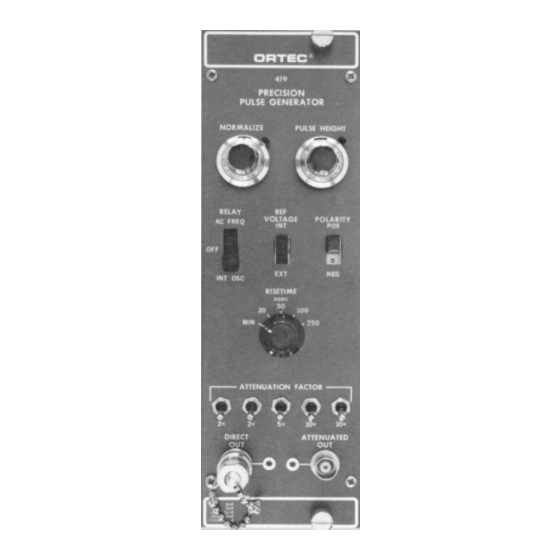
- Page 1 Model 419 Precision Pulse Generator Operating and Service Manual ® Printed in U.S.A. ORTEC Part No. 733180 1202 Manual Revision C...
- Page 2 In the event ORTEC fails to manufacture or deliver items called for in this agreement or purchase order, ORTEC’s exclusive liability and buyer’s exclusive remedy shall be release...
-
Page 3: Table Of Contents
CONTENTS WARRANTY ............... ii SAFETY INSTRUCTIONS AND SYMBOLS . -
Page 4: Safety Instructions And Symbols
SAFETY INSTRUCTIONS AND SYMBOLS This manual contains up to three levels of safety instructions that must be observed in order to avoid personal injury and/or damage to equipment or other property. These are: DANGER Indicates a hazard that could result in death or serious bodily harm if the safety instruction is not observed. -
Page 5: Safety Warnings And Cleaning Instructions
SAFETY WARNINGS AND CLEANING INSTRUCTIONS DANGER Opening the cover of this instrument is likely to expose dangerous voltages. Disconnect the instrument from all voltage sources while it is being opened. WARNING Using this instrument in a manner not specified by the manufacturer may impair the protection provided by the instrument. -
Page 7: Description
ORTEC 400 Series. terms of equivalent energy deposited in a detector. The 419 has a rise time control on the front panel to 1.2. BASIC FUNCTION simulate... -
Page 8: Specifications
2. SPECIFICATIONS PERFORMANCE POLARITY A 2-position slide switch selects either polarity for the output pulses when they are based on use of the internal reference. PULSE AMPLITUDE Output peak adjustable from 0 to ±l V; using the charge terminator supplied, this RISE TIME A 5-position rotary switch selects the is 0 to 2 picocoulombs and is equivalent to 0 to 44 rise time shaping for the output pulses to simulate... -
Page 9: Installation
IMPEDANCE CONSIDERATIONS There are three general methods of termination If the 419 is inserted in a bin which has no ac that are used. The simplest of these is shunt voltage, the unit will operate correctly on the INT. -
Page 10: Operating Instructions
100- terminator will be of the order of 93 and this correctly matches the cable impedance. For your convenience, ORTEC stocks the proper terminators and BNC tees, or you can obtain them from a variety of commercial sources. 4. OPERATING INSTRUCTIONS forming circuitry. -
Page 11: Connector Data
419. The charge-sensitive preamplifier input. Also, with the external reference voltage may be any arbitrary... - Page 12 Hewlett-Packard 400D, are required for this measurement. Connect a suitable capacitor to the input to simulate the detector The 419 pulser may easily be calibrated so that the capacitance desired. To obtain the resolution maximum PULSE HEIGHT dial reading (1000...
- Page 13 419 as follows: MEASUREMENTS USING A PULSE HEIGHT ANALYZER 1. Select the energy of interest with the 419, and Probably the most convenient method of making set the linear amplifier and biased amplifier gain resolution measurements is with a pulse height and bias level controls so that the energy is in a analyzer as shown in Fig.
- Page 14 2. Calibrate the analyzer in keV per channel, using a given detector bias can be determined in the the pulser. (Full scale on the pulser dial is 10 MeV same manner by connecting a detector to the when calibrated as described in "Calibrating the preamplifier input.
- Page 15 amplifier. By observing the waveshape at point A As an example of this method, assume that the (Fig. 4.5), the fine gain of the amplifier and the amplifier under test has essentially zero output attenuation controls should be adjusted until a null impedance.
-
Page 16: Maintenance
The attenuator switches in the measurements of temperature stability. 419 have an accuracy controlled by 0.1% metal film resistors and can be used to digitally check the linearity of the spectrometer. In addition to the... -
Page 17: Adjustment Of Internal Oscillator Frequency
5.3. ADJUSTMENT OF DECAY TIME OF OUTPUT PULSE With an 800-mV output pulse at the attenuated test As the 419 is normally supplied, the decay time of point, measure the 10-90% rise time for all the output pulse is essentially fixed. The output positions of the RISETIME switch. -
Page 18: Tabulated Test Point Voltages
TROUBLESHOOTING added directly onto the etched circuit board. Decay If the 419 is suspected of malfunctioning, it is time constants as short as 10 s can be essential to verify such malfunctioning in terms of accomplished quite easily. - Page 19 *16 +12 V Coaxial 1 2 V Coaxial Spare bus Coaxial Reserved bus *41 117 V ac (neutral) Spare *42 High-quality ground Spare Ground guide pin Reserved Pins marked (*) are installed and wired in ORTEC’s 4001A and 4001C Modular System Bins.
Need help?
Do you have a question about the 419 and is the answer not in the manual?
Questions and answers