Table of Contents
Advertisement
Advertisement
Table of Contents

Summary of Contents for FG Wilson PowerWizard 1.1
- Page 1 PowerWizard 1.1, 1.1+ & & 2.1 Generating Set Control Technical Manual...
-
Page 2: Table Of Contents
ConTenTS IMPorTanT SafeTy InforMaTIon General InforMaTIon Introduction ..............................6 applications ..............................6 PowerWizard Variations ..........................6 PowerWizard Control Module Description ....................7 USer InTerfaCe oVerVIeW Hot Keys ................................8 2.2 Control Keys ..............................8 2.3 navigation Keys .............................. 8 2.4 event Keys and Indicators ..........................9 DeTaIleD oPeraTIon PowerWizard Menu Trees .......................... - Page 3 SeTPoInT ProGraMMInG Digital Input Programming ......................... 24 5.1.1 Digital Inputs ...................................24 5.1.2 Dedicated Digital Inputs .............................24 5.1.3 Programmable Digital Inputs ........................... 25 relay and Digital output Programming ....................26 analogue Input Programming ........................29 reTrofITTInG PoWerWIzarDS eST availability and licensing ........................31 6.2 flash files and field replacement files ....................
- Page 4 aPPenDIx a – SPn/fMI lIST aPPenDIx B – SeTPoInT TaBleS Control ................................43 1.1.1 Automatic Start/Stop ..............................43 1.1.2 AVR Desired Voltage ..............................44 1.1.3 Governor Desired Engine Speed ..........................44 engine Monitor / Protect ..........................44 1.2.1 Battery Voltage Monitor ............................. 44 1.2.2 Crank / Start Counter ..............................
-
Page 5: Important Safety Information
IMPorTanT SafeTy InforMaTIon Most accidents that involve product operation, maintenance and repair are caused by failure to observe basic safety rules or precautions. An accident can often be avoided by recognizing potentially hazardous situations before an accident occurs. A person must be alert to potential hazards. This person should also have the necessary training, skills and tools to perform these functions properly. -
Page 6: General Information
1.3 PowerWizard Variations Some of the different features of the three versions, PowerWizard 1.1, PowerWiard 1.1+ and PowerWizard 2.1 are listed in Table 1. Controllers Series features PowerWizard... -
Page 7: Powerwizard Control Module Description
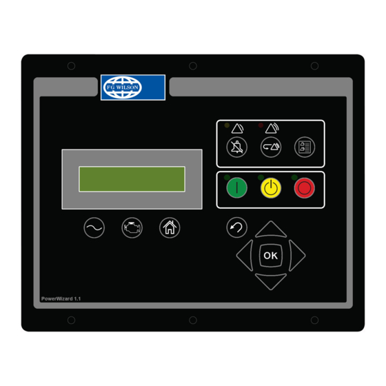
1.4 PowerWizard Control Module Description Display screen AC overview key Engine overview key Main menu or home key Alarm acknowledge key Event reset key Event log key Auto key Stop key Run key Escape key Up key Right key OK or Enter key Down key Left key figure 2: PowerWizard Control Module Description... -
Page 8: User Interface Overview
2. User Interface overvIew 2.1 Hot Keys AC Overview key – The AC Overview key will navigate the display to the first screen of AC information. The AC Overview information contains various AC parameters that summarise the electrical operation of the generating set. (Use the up / down keys to navigate within the AC parameters.) Engine Overview key –... -
Page 9: Event Keys And Indicators
2.4 event Keys and Indicators Yellow Warning Light – A flashing yellow light indicates that there are unacknowledged active warnings. A solid yellow light indicates that there are acknowledged warnings active. If there are any active warnings, the yellow light will change from flashing yellow to solid yellow after the Alarm Acknowledge key is pressed. -
Page 10: Detailed Operation
Gen Over/Under Voltage Contrast Pressure Digital Inputs Temperature Relay Outputs Lamp Test Digital Outputs Language Analog Inputs figure 3: PowerWizard 1.1, 1.1+ Menu Tree Main Menu Digital Inputs Event Log PowerWizard 2.1 View Relay Outputs Engine Overview Control Digital Outputs... -
Page 11: Technical Operation
3.2 Technical operation 3.2.1 engine Starting Sequence The PowerWizard receives an engine start signal. The signal will be one of three. • The operator presses the Run key • The control is in auto and the remote initiate digital input becomes active •... -
Page 12: Event Viewing
3.2.5 event Viewing There are two ways to view events. Pressing the EVENT LOG key navigates directly to the ACTIVE EVENTS menu. The other way is to use the Main Menu: From the MAIN MENU / VIEW, highlight “EVENT LOGS” and press the Enter key. The ACTIVE EVENTS menu will be displayed. In this menu, a list of all installed ECMs will also be displayed with the number of the total of present and active events. -
Page 13: Real Time Clock Programming (Powerwizard 2.1)
DroP To MIn leVel – used to return the current security level to the lowest level setup. Highlight and press OK to drop to minimum level security. If no Levels 1 or 2 passwords are setup the minimum level will be 2. If a Level 2 password is setup, the minimum level will be 1 and if a Level 1 password is setup the minimum level will be 0. -
Page 14: Fuel Transfer (Powerwizard 2.1)
3.6 fuel Transfer (PowerWizard 2.1) Fuel pump in connection with fuel level measurement can be controlled to transfer diesel to the fuel tank. In order to set the Fuel Transfer operation: MAIN MENU > CONTROL > FUEL TRANSFER To start or stop fuel pump, highlight the PUMP CONTROL then press the OK key. Use the cursor key to select START FUEL PUMP or STOP FUEL PUMP and press the OK key. -
Page 15: Installation
4. InstallatIon 4.1 Power requirements The PowerWizard series of generating set controls require a nominal voltage of 12 Vdc or 24 Vdc. If batteries are used for operating power, a charging source such as an alternator or battery charger is necessary to maintain a stable supply voltage. Under steady state operation, the PowerWizard controllers on 12V sets have less than 1A current draw (not including any relay loads). -
Page 16: Location Considerations
4.2 location Considerations When selecting a location for mounting the PowerWizard generating set control, consider the following: • Protection from high-voltage and high-current devices • Protection from devices which may produce electromagnetic interference • Protection from excessive vibration. The controls are designed to withstand normal generating set vibrations. The controls should not be mounted directly to the engine block. -
Page 17: Winding Connections
CT A CT B CT C MODBUS J1939 CAN DATA LINKS DATA LINK 13 11 9 31 47 57 39 50 34 42 62 64 63 5 3 4 67 66 POWERWIZARD 2.1 0-600 VAC 0-5A AC LCD DISPLAY DISCRETE SINKING OUTPUT 1 BATTERY (-) BATTERY (+) Rly1... -
Page 18: Transformer Connections
Phase A Phase B Phase C Nuetral figure 10: Three phase 3-wire Delta. Phase A Phase B Phase C Nuetral figure 11: Single phase 3-wire (Double Delta) Phase A Phase B Phase C Nuetral figure 12: Single phase 2-wire (Double Delta) 4.5 Transformer Connections The PowerWizard can monitor generator output voltages in the range of 80VAC to 600VAC. -
Page 19: Data Links
POWERWIZARD Phase A Phase B Phase C figure 14: open Delta Configuration of external Potential Transformers (PT) on the 3-wire Delta connected Generating Set POWERWIZARD Phase A Phase B Phase C Neutral figure 15: open Delta Configuration of external Potential Transformers (PT) on the 4-wire Wye connected Generating set 4.6 Data links The PowerWizard supports up to 3 different data links:... - Page 20 The maximum allowable trunk length is 130 ft (40 m) and the maximum drop length is 3 ft (1 m). The CAN network requires a termination resistor on the extreme ends of the main trunk. The topology for the PowerWizard 1.1 and 1.1+ is illustrated in Figure 11.
-
Page 21: Accessary J1939 Data Link
4.6.2 accessary J1939 Data link The Accessory J1939 Data Link is supported by the PowerWizard 2.1. The Accessory Data Link is used for local or remote communication among modules associated with a single generating set. This includes annunciators and other expansion modules. The Accessory J1939 Data Link utilizes the same SAE standards as CAN1. Wiring Pin # name... -
Page 22: Optional Modules
CAN1 indicates the connection for the PowerWizard Primary J1939 data link and CAN2 indicates the connection for the PowerWizard Accessory J1939 data link. The PowerWizard 1.1 and 1.1+ only supports the Primary J1939 data link. For more information on the Primary and Accessory data links, refer to the Data Links section. - Page 23 PowerWizard 1.1,1.1+ CAN 1 133 FT Maximum figure 18: PowerWizard 1.1,1.1+ and annunciator Connection PowerWizard 2.1: Supports one Annunciator module using CAN1 and up to three Annunciators using CAN2 Annunciator 1 PowerWizard 2.1 3 ft Maximum CAN 2 800 ft Maximum...
-
Page 24: Setpoint Programming
There are eight digital inputs on the PowerWizard. The first and second digital inputs are dedicated for the emergency stop and remote initiate function. The other 6 digital inputs on the PowerWizard 2.1 (4 digital inputs on PowerWizard 1.1) can be programmed for: Disabled, Command or Status, System Events and SCADA Datalink. -
Page 25: Programmable Digital Inputs
5.1.3 Programmable Digital Inputs The inputs can be programmed through the following menu options: MAIN MENU > CONFIGURE > INPUTS & OUTPUTS > DIGITAL INPUTS The usage type can be selected from the following: • Disabled Command or Status; refer to the “Command or Status” section below •... -
Page 26: Relay And Digital Output Programming
5.2 relay and Digital output Programming The PowerWizard 1.1 and 1.1+ have six type-A relays. The PowerWizard 2.1 has eight relays. Six of these are type-A relays and the other two are type-C relays. Type-A is defined as one normally-open contact plus common. Type-C is defined as two contacts, normally-open and normally-closed plus common. - Page 27 The procedures that must be performed in order to program the outputs depend on the usage type for the output. Usage types are activated from the menu options below. MAIN MENU > CONFIGURE > INPUTS & OUTPUTS > RELAY OUTPUTS MAIN MENU >...
- Page 28 V&Hz Within limits – The normal operating range is defined as being neither above the high warning or shutdown thresholds, nor below the low warning or shutdown thresholds. Activated when measured generator voltage and frequency (that is calculated as a percentage of rated voltage and frequency) are both within the normal operating range. This deactivates when either the measured generator voltage or the frequency are outside the normal operating range.
-
Page 29: Analogue Input Programming
5.3 analogue Input Programming PowerWizard 2.1 and 1.1+ have three analogue input channels and PowerWizard 1.1 has two. For a Mechanical Unit Injector Engine (MUI), two of the inputs are dedicated to monitor the engine coolant temperature and the engine oil pressure. The Analogue Input #3 has a default configuration to "disabled". - Page 30 2. Voltage sender For a voltage sender, the desired voltage range and corresponding data range need to be selected. The available voltage ranges are given in Table 10. The minimum and maximum data points can be set under the menu of DATA RANGE MIN and DATA RANGE MAX.
-
Page 31: Retrofitting Powerwizards
If a Field Replacement File that was created for a PowerWizard 1.1 is loaded onto a PowerWizard 2.1, some of the items on the PowerWizard 2.1 will not be configured. To configure these items open EST and select Configuration (SERVICE →... - Page 32 Using eST to load flash files It is recommended to use the latest version of the service tool. While any version from 2004A onwards should work, it is easier to follow screen shots and menu navigation if the latest version is used. Open EST Winflash (This should be a separate option to “Electronic Service Tool”...
- Page 33 Using eST to load field replacement files Open EST ECM Replacement by selecting the Service » Copy Configuration » ECM Replacement menu item, as shown in the figure below. Select the Field replacement File (.xml file) that you want to load as shown in the screen below. The following screen will then be displayed showing the configuration values.
-
Page 34: Possible Est Error Messages, Their Cause And Suggested Action
6.3 Possible eST error messages, their cause and suggested action “The communication adapter was unable to connect to the J1939 data link.” Cause: EST was unable to see the Communication adaptor on the port it is expecting it to be connected to •... -
Page 35: Step Through Guides
7. step throUGh GUIDes 7.1 reduced Power Mode (rPM) Under steady state operation, the PowerWizard controllers on 12V generating sets have less than 1A current draw (not including any relay loads). This value will be lower for controllers on 24V generating sets. This can be reduced by approximately a factor of 7 by using the Reduced Power Mode (RPM). -
Page 36: Service Maintenance Interval
A Level 3 password is required to allow the user to enter this screen and to enable the Reduced Power Mode. The user may also change the time delay before the Reduced Power Mode is activated by entering the screen shown below. reDUCeD PoWer MoDe Delay TIMe 30 MInS... -
Page 37: Disabling Not In Auto
7.4 Disabling noT In aUTo By default PowerWizard control panels have a generating set “not in auto” warning. This warning will be active when the control is in ‘STOP’ or ‘RUN’ mode. For certain applications it may be suitable to disable this warning. To disable “Not In Auto” perform the following. -
Page 38: Appendix A - Spn/Fmi List
appenDIx a – 1.1 SPn/fMI list event name External Tank High Fuel Level Shutdown External Tank Low Fuel Level Shutdown External Tank Fuel Level Sensor Short High External Tank Fuel Level Sensor Short Low External Tank High Fuel Level Warning External Tank Low Fuel Level Warning High Starting Air Pressure Shutdown Low Starting Air Pressure Shutdown... - Page 39 event name Engine Coolant Level Sensor Short High Engine Coolant Level Sensor Short Low High Engine Coolant Level Warning Low Engine Coolant Level Warning High Fire Extinguisher Pressure Shutdown Low Fire Extinguisher Pressure Shutdown Fire Extinguisher Pressure Sensor Short High Fire Extinguisher Pressure Sensor Short Low High Fire Extinguisher Pressure Warning Low Fire Extinguisher Pressure Warning...
- Page 40 event name Custom Event #4 High Warning Custom Event #4 Low Warning Custom Event #4 Status Custom Event #5 High Shutdown Custom Event #5 Low Shutdown Custom Event #5 High Warning Custom Event #5 Low Warning Custom Event #5 Status Custom Event #6 High Shutdown Custom Event #6 Low Shutdown Custom Event #6 High Warning...
- Page 41 event name Right Exhaust Temperature Signal Abnormal 2433 High Right Exhaust Temperature Warning 2433 Low Right Exhaust Temperature Warning 2433 High Left Exhaust Temperature Shutdown 2434 Low Left Exhaust Temperature Shutdown 2434 Left Exhaust Temperature Sensor Short High 2434 Left Exhaust Temperature Signal Abnormal 2434 Left Exhaust Temperature Sensor Short Low 2434...
- Page 42 event name Custom Event #45 Status 3920 Custom Event #46 Status 3921 Custom Event #47 Status 3922 Custom Event #48 Status 3923 Custom Event #49 Status 3924 Custom Event #50 Status 3925 Custom Event #51 Status 3926 Custom Event #52 Status 3927 Custom Event #53 Status 3928...
-
Page 43: Appendix B - Setpoint Tables
1.2 Control 1.2.1 automatic Start/Stop Setpoints > Control > automatic Start/Stop Setpoint name Units Description Value Value Engine start fault protection activation delay Time delay to prevent shut down during start up time from low oil pressure etc. Amount of time the control energizes (cranks) the Crank Duration starting motor Time the control de-energizes the starting motor... -
Page 44: Avr Desired Voltage
1.2.2 aVr Desired Voltage Setpoints > Control > aVr Desired Voltage Setpoint name Units Description Value Value The Maximum Generator Output voltage Bias Percent is the Maximum Generator Voltage maximum value above and below the Nominal Voltage that the Output Bias Percentage control will send a request for when adjusting the voltage from the control screen The Generator Nominal Output Voltage is the desired output... -
Page 45: Engine Speed Monitor
1.3.3 engine Speed Monitor Setpoints > engine Monitor / Protect > engine Speed Monitor Setpoint name Units Description Value Value Flywheel Teeth Engine Over Speed Shutdown Threshold 4330 Set to 118% of rated speed Engine Under Speed Warning Event Threshold 4330 Set to 86% of rated speed Engine Under Speed Warning Event Notification Delay... -
Page 46: Generator Monitor / Protect
1.5 Generator Monitor / Protect 1.5.1 enhanced generator monitor Setpoints > Generator Monitor / Protect > enhanced Generator Monitor factory Setpoint name Units Description Value Value Default Set to “Installed” when a Generator Winding Temperature Sensor Value List temperature module is installed Installation Status on the accessory data link Number of Generator Bearing Temperature... -
Page 47: Generator Over Current
1.5.4 Generator over current Setpoints > Generator Monitor/Protect > Generator over Current Setpoint name Units factory Description Value Value Default Generator Definite Time Over Current (Amp) Warning Event Percentage Threshold for the Over Current Warning Threshold Time multiplier setpoint (TM) used in Generator Inverse Time Over Current 0.05 10.00... -
Page 48: Network
1.6 network Setpoints > network > Data link - SCaDa Setpoint name Max Value Units Description Value SCADA Data Link Baud Rate 2400 57600 SCADA Data Link Parity Select “None” “Odd” or “Even” SCADA Data Link Slave Address SCADA Data Link Access Password 0xfffff SCADA Data Link Connection Timeout Interval 3600.0... -
Page 49: Inputs & Outputs
1.8 Inputs & outputs 1.8.1 Digital Inputs Refer to the Digital Inputs section. 1.8.2 Digital outputs Refer to the Relay and Digital Outputs section. 1.8.3 relay outputs Refer to the Relay and Digital Outputs section. 1.8.4 analogue Inputs The Analogue input coverts a resistive or Analogue voltage sender value to units and detects a high or low condition on the sender input.
Need help?
Do you have a question about the PowerWizard 1.1 and is the answer not in the manual?
Questions and answers
thomasryan