Table of Contents
Advertisement
Quick Links
Advertisement
Table of Contents

Related Manuals for Cambium PTP 450

Summary of Contents for Cambium PTP 450
- Page 1 Cambium PTP 450 Configuration and User Guide System Release 13.4...
-
Page 2: Ptp 450 Module Essential Information
PTP 450 Configuration and User Guide PTP 450 module essential information Default IP Address for Management 169.254.1.1 GUI Access Default Administrator Username admin Default Administrator Password (no password) Refer “Updating the software version and PTP 450 Configuration Software Upgrade Procedure using CNUT”... - Page 3 While reasonable efforts have been made to assure the accuracy of this document, Cambium Networks assumes no liability resulting from any inaccuracies or omissions in this document, or from use of the information obtained herein. Cambium reserves the right to make changes to any products described herein to improve reliability,...
-
Page 4: Safety And Regulatory Information
Exercise extreme care when working at heights. Grounding and protective earth PTP 450 units must be properly grounded to protect against lightning. It is the user’s responsibility to install the equipment in accordance with national regulations. In the USA, follow Section 810 of the National Electric Code, ANSI/NFPA No.70-1984... - Page 5 RF exposure near the antenna Radio frequency (RF) fields are present close to the antenna when the transmitter is on. Always turn off the power to the PTP 450 unit before undertaking maintenance activities in front of the antenna. Minimum separation distances Install the BHM or BHS so as to provide and maintain the minimum separation distances from people.
-
Page 6: Table Of Contents
PTP 450 Configuration and User Guide Contents Contents PTP 450 module essential information ............... ii Safety and regulatory information ..............iv Important safety information ................iv Important regulatory information ................. v About This Configuration and User Guide ............xv General information ....................xvi Version information .................... - Page 7 Contents PTP 450 Configuration and User Guide SNMP ....................... 1-25 Network Time Protocol (NTP) ................. 1-25 Wireless Manager (WM) .................. 1-26 Software upgrade .................... 1-27 Further reading on system management ............1-27 Chapter 2: Using Informational tabs of the GUI .......... 2-1 Viewing General Status tab (BHM) .................
- Page 8 Regulatory planning ....................4-2 Obeying Regulatory limits ................. 4-2 Conforming to the limits ..................4-2 Network migration planning ..................4-3 Example PTP 450 deployment scenario ............. 4-3 Sector capacity ....................4-5 Site planning ......................4-10 BHM or BHS site selection ................4-10 Power supply site selection ................
- Page 9 Configuring management IP by DHCP ............4-49 Planning for airlink security ................4-49 Planning for SNMP security ................4-49 Ordering components .................... 4-52 PTP 450 component part numbers ..............4-52 Chapter 5: Legal information ..............5-1 Cambium Networks end user license agreement ............ 5-2 Acceptance of this agreement ................
- Page 10 PTP 450 Configuration and User Guide Contents Type approvals ....................6-15 DFS for 5.4 GHz Radios ................... 6-16 Country Codes and available spectrum ............6-18 FCC compliance testing ................... 6-32 FCC and ICC IDs and certification numbers ........... 6-32 Listen Before Talk (LBT) for 3.6 GHz Radios........... 6-38 Listen Before Talk (LBT) for 5.4 GHz Radios...........
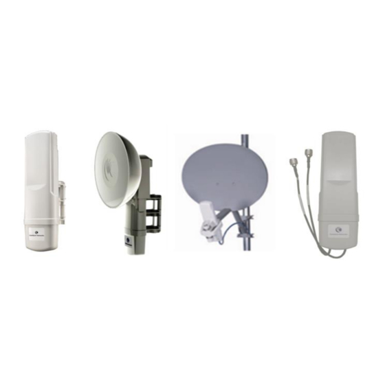
- Page 11 PTP 450 Configuration and User Guide List of Figures Figure 1 Line of Sight Diagram..................1-2 Figure 2 PTP 450 Series BHM / BHS ................1-5 Figure 3 Radiated BH Unit.................... 1-5 Figure 4 Connectorized BH Unit ................... 1-5 Figure 5 BHM/BHS interfaces ..................1-6 Figure 6 Radio diagnostic LEDs, viewed from unit front ..........
- Page 12 Figure 44 One unsynchronized BHM in cluster resulting in self-interference ... 4-30 Figure 45 GPS timing throughout the network ............4-31 Figure 46 Cambium network management domain ............ 4-33 Figure 47 BHM/BHS Add User tab of account page ........... 4-39 Figure 48 Delete User tab of the BHM/BHS ...............
- Page 13 PTP 450 Configuration and User Guide List of Tables Table 1 PTP 450 frequency variants ................1-4 Table 2 BHM/BHS interface descriptions and cabling – 3.5 GHz, 3.6 GHz, 5 GHz ..1-7 Table 3 BHM LED descriptions ..................1-8 Table 4 BHS LED descriptions ..................
- Page 14 Table 54 BHM physical specifications ................6-2 Table 55 PTP 450 wireless specifications ..............6-7 Table 56 PTP 450 Ethernet bridging specifications ............6-8 Table 57 PTP 450 safety compliance specifications ............6-9 Table 58 EMC emissions compliance ................6-9 Table 59 Power Compliance Margins .................
-
Page 15: About This Configuration And User Guide
About This Configuration and User Guide This guide describes the configuration of the Cambium PTP 450 Series of point-to-point wireless equipment deployment. It is intended for use by the system administrator. After the initial general and legal information, the guide begins with a set of tasks to complete a basic configuration of the equipment. -
Page 16: General Information
Cambium main website http://www.cambiumnetworks.com/ Sales enquiries sales@cambiumnetworks.com Email support support@cambiumnetworks.com RMA Inquiries rma@cambiumnetworks.com Telephone numbers For full list of Cambium support telephone numbers, see: http://www.cambiumnetworks.com/support/contact-support Address Cambium Networks 3800 Golf Road, Suite 360 Rolling Meadows, IL 60008 pmp-0815 (August 2015) - Page 17 It is recommended that all personnel engaged in such activities be properly trained. Cambium disclaims all liability whatsoever, implied or express, for any risk of damage, loss or reduction in system performance arising directly or indirectly out of the failure of the customer, or anyone acting on the customer's behalf, to abide by the instructions, system parameters or recommendations made in this document.
-
Page 18: Problems And Warranty
Search this document and the software release notes of supported releases. Visit the support website. http://www.cambiumnetworks.com/support Ask for assistance from the Cambium product supplier. Gather information from affected units such as: The IP addresses and MAC addresses. - Page 19 PTP 450 Configuration and User Warranty Cambium’s standard hardware warranty is for one (1) year from date of shipment from Cambium or a Cambium distributor. Cambium warrants that hardware will conform to the relevant published specifications and is free from material defects in material and workmanship under normal use and service.
-
Page 20: Security Advice
PTP 450 Configuration and User Guide Security advice Security advice Cambium Networks systems and equipment provide security parameters that can be configured by the operator based on their particular operating environment. Cambium recommends setting and using these parameters following industry recognized security practices. -
Page 21: Warnings, Cautions And Notes
PTP 450 Configuration and User Warnings, cautions and notes The following describes how warnings and cautions are used in this document and in all documents of the Cambium Networks document set. Warnings Warnings precede instructions that contain potentially hazardous situations. Warnings are used to alert the reader to possible hazards that could cause loss of life or physical injury. -
Page 22: Chapter 1: Product Description
Chapter 1: Product Description This chapter provides a high level description of the PTP 450 product. It describes in general terms the function of the product, the main product variants and typical deployment. It also describes the main hardware components. -
Page 23: Overview Of Ptp 450
Cambium PTP 450 Series networks are designed for wireless point-to-point links in the licensed 3.6 GHz, 3.6 GHz, lightly licensed 3.65 GHz, 5.4 GHz and 5.8 GHz bands. Users must ensure that their configuration and usage of PTP 450 Series complies with local operating regulations. -
Page 24: Typical Deployment
After ordering a BH unit, the customer can decide, via software configuration, if this unit is a BHM (Backhaul Master) or a BHS (Backhaul Slave). The radio link operates on a single frequency channel using Time Division Duplex (TDD). Applications for the PTP 450 Series include: Enterprise Access ... -
Page 25: Table 1 Ptp 450 Frequency Variants
PTP 450 Configuration and User Guide Overview of PTP 450 Product variants The PTP 450 Series is available in the following product variants: BH unit can be configured as a BHM or a BHS. Table 1 PTP 450 frequency variants... -
Page 26: Ptp 450 Backhaul Radio
PTP 450 Backhaul Radio PTP 450 Configuration and User PTP 450 Backhaul Radio The PTP 450 link requires two Backhaul Radios in following configurations: Backhaul Master (BHM) Backhaul Slave (BHS) These radios are a self-contained unit that houses both radio and networking electronics. It is supplied in a connectorized or radiated configuration. -
Page 27: Bhm/Bhs Interfaces
PTP 450 Configuration and User Guide PTP 450 Backhaul Radio 3.5 GHz and 3.6 GHz PTP 450 BH units have a different appearance from the existing 5 GHz PTP 450 BHSs. 3.5 GHz and 3.6 GHz units are compatible only with reflector dish and not the LENS. -
Page 28: Table 2 Bhm/Bhs Interface Descriptions And Cabling - 3.5 Ghz, 3.6 Ghz, 5 Ghz
PTP 450 Backhaul Radio PTP 450 Configuration and User Table 2 BHM/BHS interface descriptions and cabling – 3.5 GHz, 3.6 GHz, 5 GHz Interface Function Cabling Power-over-Ethernet, Ethernet Ethernet RJ45 Cable communications (management and data) Default Default Plug port Default plug -45 degree RF connection to 3.5 GHz... -
Page 29: Bhm/Bhs Diagnostic Leds
PTP 450 Configuration and User Guide PTP 450 Backhaul Radio BHM/BHS diagnostic LEDs The diagnostic LEDs are as shown in Figure Figure 6 Radio diagnostic LEDs, viewed from unit front BHM LED Display LED Labels LNK/5 ACT/4 GPS/3 SES/2 SYN/1 The LED color helps distinguish the position of LED. -
Page 30: Table 4 Bhs Led Descriptions
PTP 450 Backhaul Radio PTP 450 Configuration and User BHS LEDs The BHS LEDs provide different status of radio based on the operating modes. A BHS in “operating” mode registers and passes the traffic normally. A BHS in “aiming” mode does not register or pass the traffic, but displays (via LED panel) the strength of received radio signals (based on radio channel selected via Tools =>... -
Page 31: Mounting Brackets
For mounting PTP 450 BHSs, Cambium Networks offers the SMB1A mounting bracket. Network connection The network connection to a PTP 450 Series BHM/BHS is made via a 10 BaseT or 100 BaseT Ethernet connection. The power is provided to the BHM/BHS over the Ethernet connection using a proprietary powering technique. -
Page 32: Cabling And Lightning Protection
The Radio provides a grounding lug for grounding to the tower or support structure. The PTP 450 Series is not designed to survive direct lightning strikes. For this reason the unit must not be installed as the highest point in a localized area. -
Page 33: Wireless Operation
PTP 450 Configuration and User Guide Wireless operation Wireless operation This section describes how the PTP 450 wireless link is operated, including modulation modes, power control and security. Time division duplexing The system uses Time Division Duplexing (TDD) – one channel alternately transmits and receives rather than using one channel for transmitting and a second channel for receiving. -
Page 34: Ofdm And Channel Bandwidth
5.8 GHz only), 7 MHz (3.5 GHz and 3.6 GHz only), 10 MHz or 20 MHz. Link operation – Dynamic Rate Adapt PTP 450 Series products offer eight levels or speeds of operation – 2X MIMO-B and 1X MIMO-A (QPSK), 4X MIMO-B and 2X MIMO-A (16-QAM), 6x MIMO-B and 3X MIMO-A (64- QAM) and 8X MIMO-B and 4X MIMO-A (265-QAM). -
Page 35: Table 6 Range Details - Dynamic Rate Adapt, 5.4 Ghz
PTP 450 Configuration and User Guide Wireless operation Table 6 Range details – Dynamic Rate Adapt, 5.4 GHz Performance Details Product Parameter QPSK- QPSK- 16-QAM- 64-QAM- 256-QAM- Modulation MIMO A MIMO B MIMO B MIMO B MIMO B with Integrated 3.7 mi /... -
Page 36: Table 7 Range Details - Dynamic Rate Adapt, 5.8 Ghz
(no fade antenna margin) – 5 † PTP 450 devices include a dual polar antenna; Channel A (Vertical) and Channel B (Horizontal). Listed receive sensitivity corresponds to single-channel readings. ‡ Maximum setting of Max capability parameter is 40 mi. pmp-0815 (August 2015) -
Page 37: Table 8 Range Details - Dynamic Rate Adapt, 3.5 Ghz
PTP 450 Modulation SISO A MIMO B MIMO B MIMO B MIMO B § PTP 450 devices include a dual polar antenna; Channel A (Vertical) and Channel B (Horizontal). Listed receive sensitivity corresponds to single-channel readings. 1-16 pmp-0815 (August 2015) - Page 38 Wireless operation PTP 450 Configuration and User Performance Details Product Parameter with 8.8 mi / 6.3 mi / 2.9 mi / 1.4 mi / 0.5 mi / Integrated 3.5GHz 14.1 km 10.0 km 4.6 km 2.2 km 0.7 km Max. LOS...
- Page 39 126.9 Channel Budget, Integrated 7 MHz 115.5 (dB) Channel 5 MHz Channel PTP 450 devices include a dual polar antenna; Channel A (-45 deg.) and Channel B (+45 deg.). Listed receive sensitivity corresponds to single-channel readings. 1-18 pmp-0815 (August 2015)
-
Page 40: Table 9 Range Details - Dynamic Rate Adapt, 3.6 Ghz
Wireless operation PTP 450 Configuration and User Table 9 Range details – Dynamic Rate Adapt, 3.6 GHz Performance Details Product Parameter QPSK- QPSK- 16-QAM- 64-QAM- 256-QAM- Modulation MIMO A MIMO B MIMO B MIMO B MIMO B with Integrated 7.6 mi / 5.4 mi /... -
Page 41: Adaptive Modulation
‡‡ PTP 450 devices include a dual polar antenna; Channel A (-45 deg.) and Channel B (+45 deg.). Listed receive sensitivity corresponds to single-channel readings. 1-20... -
Page 42: Cyclic Prefix
2.5 ms or 5.0 ms. Encryption The Cambium PTP 450 Series supports optional encryption for data transmitted over the wireless link. The PTP 450 Series supports the following forms of encryption for security of the wireless link: DES (Data Encryption Standard): An over-the-air link encryption option that uses secret 56-bit keys and 8 parity bits. -
Page 43: System Management
Canopy Network Updater Tool (CNUT) software Web server The PTP 450 management agent contains a web server. The web server supports access via the HTTP interface. Web-based management offers a convenient way to manage the PTP 450 equipment from a locally connected computer or from a network management workstation connected through a management network, without requiring any special management software. -
Page 44: Figure 8 Bhm Web-Based Management Screenshot
System management PTP 450 Configuration and User Figure 8 BHM web-based management screenshot pmp-0815 (August 2015) 1-23... - Page 45 PTP 450 Configuration and User Guide System management Web pages The web-based management interfaces provide comprehensive Web-based fault, Configuration, Performance and Security management functions organized into the following web-pages and groups: BHM web-pages: Home: The Home web page reports the General Status, Session Status, Remote Subscriber status, Event Log information, Network Interface status and Layer 2 Neighbor information.
-
Page 46: Snmp
If an NTP server connection is available, the clock can be set to synchronize with the server time at regular intervals. PTP 450 devices may receive NTP data from a CMM3 or CMM4 module, an NTP server configured in the system’s management network. -
Page 47: Wireless Manager (Wm)
BHM as an NTP server. Wireless Manager (WM) Cambium Networks Wireless Manager 4.0 is recommended for managing PTP 450 networks. You can achieve better uptime through better visibility of your network with the Cambium Wireless Manager. This network management software tool offers breakthrough... -
Page 48: Software Upgrade
System management PTP 450 Configuration and User Canopy Network Updater Tool (CNUT) CNUT (Canopy Network Updater Tool) is the stand-alone software update tool for PTP 450 Series products. The Canopy Network Updater Tool has the following features: Automatically discovers all network elements ... -
Page 49: Chapter 2: Using Informational Tabs Of The Gui
Chapter 2: Using Informational tabs of the GUI The General Status tab provides information on the operation of BHM and BHS. This is the tab that opens by default when you access the GUI. Example of BHM and BHS General Status tab is explained in the following sections. pmp-0851 (August 2015) -
Page 50: Viewing General Status Tab (Bhm)
PTP 450 Configuration and User Guide Viewing General Status tab (BHM) Viewing General Status tab (BHM) The General Status tab provides information on the operation of this BHM. This is the tab that opens by default when you access the GUI of the BHM. Example of BHM General Status tab is displayed below. -
Page 51: Table 10 Bhm General Status Attributes
This field indicates whether the configured Country Code and radio frequency are compliant with respect to their compatibility. PTP 450 equipment shipped to the United States is locked to a Country Code setting of “United States”. Units shipped to regions other than the United States must be configured with the corresponding Country Code to comply with local regulatory requirements. - Page 52 PTP 450 Configuration and User Guide Viewing General Status tab (BHM) Attribute Meaning Channel The size in MHz of the operating channel. Bandwidth Cyclic Prefix OFDM technology uses a cyclic prefix, where a portion of the end of a symbol (slot) is repeated at the beginning of the symbol to allow multi-pathing to settle before receiving the desired data.
- Page 53 Viewing General Status tab (BHM) PTP 450 Configuration and User Attribute Meaning Data Slots Up This field lists the number of slots used for uplink data transmission. Site Name This field indicates the name of the physical module. You can assign or change this name in the SNMP tab of the BHS Configuration page.
-
Page 54: Viewing General Status Tab (Bhs)
PTP 450 Configuration and User Guide Viewing General Status tab (BHS) Viewing General Status tab (BHS) The General Status tab provides information on the operation of this BHS. This is the tab that opens by default when you access the GUI of the BHS. An example of the General Status tab of a BHS is displayed below. -
Page 55: Table 11 Bhs General Status Attributes
Viewing General Status tab (BHS) PTP 450 Configuration and User The BHS’s General Status tab provides the following read-only fields. Table 11 BHS General Status attributes Attribute Meaning Device Type This field indicates the type of the module. Values include the frequency band of the BHS, its module type and its MAC address. - Page 56 PTP 450 Configuration and User Guide Viewing General Status tab (BHS) Attribute Meaning Session Status This field displays the following information about the current session: Scanning indicates that this BHS currently cycles through the radio frequencies that are selected in the Radio tab of the Configuration page.
- Page 57 Viewing General Status tab (BHS) PTP 450 Configuration and User Attribute Meaning Data Slots Up This field lists the number of slots used for uplink data transmission. Site Name This field indicates the name of the physical module. You can assign or change this name in the SNMP tab of the BHS Configuration page.
-
Page 58: Chapter 3: Configuration
Chapter 3: Configuration This chapter describes all configuration tasks that are performed when a PTP 450 link is deployed. Precautions in Preparing for configuration on page 3-2. This section is divided into several tasks, including: Task 1: Connecting to the unit ... -
Page 59: Preparing For Configuration
PTP 450 Configuration and User Guide Preparing for configuration Preparing for configuration This section describes the checks to be performed before proceeding with unit configuration. Safety precautions during configuration All national and local safety standards must be followed while configuring the units and aligning the antennas. -
Page 60: Task 1: Connecting To The Unit
Task 1: Connecting to the unit PTP 450 Configuration and User Task 1: Connecting to the unit This task consists of the following procedures: Configuring the management PC on 3-3. Connecting to the PC and powering up on page 3-4. -
Page 61: Connecting To The Pc And Powering Up
PTP 450 Configuration and User Guide Task 1: Connecting to the unit Enter an IP address that is valid for the 169.254.X.X network, avoiding: 169.254.0.0 and 169.254.1.1 and 169.254.1.2 A good example is 169.254.1.3: Enter a subnet mask of 255.255.255.0. -
Page 62: Logging Into The Web Interface (Bhm Or Bhs)
Task 1: Connecting to the unit PTP 450 Configuration and User Logging into the web interface (BHM or BHS) To log into the BHM or BHS web interface as a system administrator, follow these instructions: Procedure 3 Logging into the web interface (BHM or BHS) Start the web browser from the management PC. -
Page 63: Figure 12 Bhm General Status Page, Administrator User Example
PTP 450 Configuration and User Guide Task 1: Connecting to the unit default admin admin Log in with the administrator Username ( ) and Password ( Figure 12 BHM General Status page, ADMINISTRATOR user example pmp-0815 (August 2015) -
Page 64: Task 2: Configuring Ip And Ethernet Interfaces
Task 2: Configuring IP and Ethernet interfaces PTP 450 Configuration and User Task 2: Configuring IP and Ethernet interfaces This task consists of the following sections: DHCP Reconnecting to the management PC VLAN tab of BHM ... -
Page 65: Vlan Tab Of Bhm
PTP 450 Configuration and User Guide Task 2: Configuring IP and Ethernet interfaces VLAN tab of BHM Figure 13 VLAN tab of BHM In the VLAN tab of BHS, you may set the following parameters. Table 12 BHM VLAN tab attributes... - Page 66 When VLAN is enabled in the BHM, the Active Configuration block provides the following details as read-only information in this tab. In the Cambium fixed wireless broadband IP network, each device of any type is automatically a permanent member of VID 1. This facilitates deployment of devices that have VLAN enabled with those that do not.
-
Page 67: Vlan Tab Of Bhs
When VLAN is enabled in the BHM, the Active Configuration block provides the following details as read-only information in this tab. In the Cambium fixed wireless broadband IP network, each device of any type is automatically a permanent member of VID 1. This facilitates deployment of devices that have VLAN enabled with those that do not. -
Page 68: Task 3: Upgrading The Software And Using Cnut
3-11. Upgrading to a new software version PTP 450 modules are upgraded using the Canopy Network Updater Tool. The Canopy Network Updater Tool (CNUT) manages and automates the software and firmware upgrade process for a Canopy radio, CMMmicro or CMM4 (but not its 14-port switch) across the network. - Page 69 PTP 450 Configuration and User Guide Task 3: Upgrading the software and using CNUT CNUT functions The Canopy Network Updater Tool has the following functions: Automatically discovers all network elements CNUT support HTTP and HTTPS Executes a UDP command that initiates and terminates the Auto-update mode within BHMs.
- Page 70 Task 3: Upgrading the software and using CNUT PTP 450 Configuration and User Network layers A typical network contains multiple layers of elements, with each layer farther from the Point of Presence. For example, BHSs are behind a BHM and thus, in this context, at a lower layer than the BHM.
- Page 71 PTP 450 Configuration and User Guide Task 3: Upgrading the software and using CNUT Upgrading a module prior to deployment To upgrade to a new software version, follow this: Procedure 5 Upgrading a module prior to deployment Go to the support website (see...
-
Page 72: Task 4: Configuring General And Unit Settings
Task 4: Configuring General and Unit settings PTP 450 Configuration and User Task 4: Configuring General and Unit settings General tab of BHM’s Configuration section Figure 15 General tab of BHM The General tab of the BHM’s Configuration section contains many of the configurable parameters that define how the BHM and the BHS in the sector operate. -
Page 73: Table 14 Bhm General Tab Attributes
PTP 450 Configuration and User Guide Task 4: Configuring General and Unit settings Table 14 BHM General tab attributes Attribute Meaning Timing Mode Allows the user to choose the mode between Timing Master and Timing Slave. Link Speed From the drop-down list of options, select the type of link speed for the Ethernet connection. - Page 74 1 and 2 in the Configuration => Radio tab). PTP 450 equipment shipped to the United States is locked to a Region Code setting of “United States”. Units shipped to regions other than the United States must be configured with the corresponding Region Code to comply with local regulatory requirements.
- Page 75 PTP 450 Configuration and User Guide Task 4: Configuring General and Unit settings Attribute Meaning Bridge Entry Specify the appropriate bridge timeout for correct network Timeout operation with the existing network infrastructure. The Bridge Entry Timeout must be a longer period than the ARP (Address Resolution Protocol) cache timeout of the router that feeds the network.
-
Page 76: Unit Settings Tab Of Bhm
Task 4: Configuring General and Unit settings PTP 450 Configuration and User Attribute Meaning Latitude Physical radio location data may be configured via the Latitude, Longitude and Height fields. Longitude Decimal Degree Latitude and Longitude is measured in while the Height Meters. - Page 77 PTP 450 Configuration and User Guide Task 4: Configuring General and Unit settings Import and Export of config file Procedure 6 Export the configuration from the GUI Login to the GUI and go to Configuration → Unit Settings. Under Download Configuration File tab, click on the “<mac>.cfg” link, where <mac>...
-
Page 78: Table 15 Bhm Unit Settings Attributes
Task 4: Configuring General and Unit settings PTP 450 Configuration and User Procedure 8 Special Headers for configuration file A "configFileParameters" section can be added to the header to control the behaviour of the device when importing configuration. "cfgFileString": "Canopy configuration file", "cfgFileVersion": "1.0",... - Page 79 PTP 450 Configuration and User Guide Task 4: Configuring General and Unit settings Attribute Meaning Undo Unit-Wide When you click this button, any changes that you made in any Saved Changes tab but did not commit by a reboot of the module are undone.
-
Page 80: General Tab Of Bhs
Task 4: Configuring General and Unit settings PTP 450 Configuration and User General tab of BHS Figure 17 General tab of BHS pmp-0815 (August 2015) 3-23... -
Page 81: Table 16 Bhs General Tab Attributes
PTP 450 equipment shipped to the United States is locked to a Region Code setting of “United States”. Units shipped to regions other than the United States must be configured with the corresponding Region Code to comply with local regulatory requirements. - Page 82 Task 4: Configuring General and Unit settings PTP 450 Configuration and User Attribute Meaning Bridge Entry Specify the appropriate bridge timeout for correct network Timeout operation with the existing network infrastructure. Timeout occurs when the BHM encounters no activity with the BHS (whose MAC address is the bridge entry) within the interval that this parameter specifies.
- Page 83 PTP 450 Configuration and User Guide Task 4: Configuring General and Unit settings Attribute Meaning Latitude Physical radio location data may be configured via the Latitude, Longitude and Height fields. Longitude Decimal Degree Latitude and Longitude is measured in while the Height Meters.
-
Page 84: Unit Settings Tab Of Bhs
Task 4: Configuring General and Unit settings PTP 450 Configuration and User Unit settings tab of BHS Figure 18 Unit Settings tab of BHS The Unit Settings tab of the BHS contains an option on how a BHS must react when it detects a connected override plug. - Page 85 PTP 450 Configuration and User Guide Task 4: Configuring General and Unit settings Attribute Meaning If Disabled is checked, then an override/default plug functions as an override plug. When the module is rebooted with the plug inserted, it can be accessed at the IP address 169.254.1.1 and no password, and all previously configured parameter values remain and are displayed.
-
Page 86: Time Tab Of Bhm
Task 4: Configuring General and Unit settings PTP 450 Configuration and User Attribute Meaning The configuration file can be either imported the full configuration or a sparse configuration containing on the items that need to be changed. If a sparse configuration file is imported, only the items in the file will be imported. -
Page 87: Table 18 Bhm Time Tab Parameters
PTP 450 Configuration and User Guide Task 4: Configuring General and Unit settings In the Time tab of BHM, you may set the following parameters: Table 18 BHM Time tab parameters Attribute Meaning NTP Server (Name The management DNS domain name may be toggled such that... - Page 88 Task 4: Configuring General and Unit settings PTP 450 Configuration and User Attribute Meaning Date This field may be used to manually set the system date of the radio. NTP Update log This field shows NTP clock update log. It includes NTP clock update Date and Time stamp along with server name.
-
Page 89: Task 5: Configuring Security
PTP 450 Configuration and User Guide Task 5: Configuring Security Task 5: Configuring Security Encrypting radio transmissions on page 3-33: to configure the unit to operate with AES or DES wireless link security Managing module access by passwords... -
Page 90: Encrypting Radio Transmissions
Task 5: Configuring Security PTP 450 Configuration and User Encrypting radio transmissions Cambium fixed wireless broadband IP systems employ the following form of encryption for security of the wireless link: DES (Data Encryption Standard): An over-the-air link encryption option that uses secret 56-bit keys and 8 parity bits. -
Page 91: Filtering Protocols And Ports
PTP 450 Configuration and User Guide Task 5: Configuring Security Once the security banner is enabled, the home login screen will be shown as below: Figure 21 Login page - Security Banner The user must accept “I have read, understood and accept the above notice(s)” to proceed with login. -
Page 92: Security Tab Of Bhm
Task 5: Configuring Security PTP 450 Configuration and User Security tab of BHM Figure 22 BHM Security tab pmp-0815 (August 2015) 3-35... -
Page 93: Table 19 Bhm Security Tab Attributes
PTP 450 Configuration and User Guide Task 5: Configuring Security In the Security tab of the BHM, you may set the following parameters Table 19 BHM security tab attributes Attribute Meaning Authentication Mode Operators may use this field to select from among the following... - Page 94 Task 5: Configuring Security PTP 450 Configuration and User Attribute Meaning Encryption Setting Specify the type of airlink security to apply to this BHM. The encryption setting must match the encryption setting of the BHSs. None provides no encryption on the air link.
- Page 95 PTP 450 Configuration and User Guide Task 5: Configuring Security Attribute Meaning Web Access The Radio supports secured and non-secured web access protocols. Select suitable web access from drop down list: HTTP Only – provides non-secured web access. The radio to be accessed via http://<IP of Radio>.
- Page 96 Task 5: Configuring Security PTP 450 Configuration and User Attribute Meaning Enable Security Enable: The Security Banner Notice will be displayed before Banner during Login login. Disable: The Security Banner Notice will not be displayed before login. Security Banner User can enter ASCII (0-9a-zA-Z newline, line-feed are allowed) Notice text up-to 1300 characters.
-
Page 97: Protocol Filtering Tab Of Bhm
PTP 450 Configuration and User Guide Task 5: Configuring Security Protocol Filtering tab of BHM Figure 23 Protocol Filtering tab of BHM 3-40 pmp-0815 (August 2015) -
Page 98: Table 20 Protocol Filtering Tab Attributes
Task 5: Configuring Security PTP 450 Configuration and User In the Protocol Filtering tab of the BHM, you may set the following parameters Table 20 Protocol filtering tab attributes Attribute Meaning Packet Filter Types For any box selected, the Protocol and Port Filtering feature blocks the associated protocol type. -
Page 99: Security Tab Of Bhs
PTP 450 Configuration and User Guide Task 5: Configuring Security Security tab of BHS Figure 24 Security tab of BHS In the Security tab of the BHS, you may set the following parameters: 3-42 pmp-0815 (August 2015) -
Page 100: Table 21 Security Tab Of Bhs
Task 5: Configuring Security PTP 450 Configuration and User Table 21 Security tab of BHS Attribute Meaning Authentication Key Only if the BHM to which this BHS registers requires an authentication, specify the key that the BHS will use when authenticating. - Page 101 PTP 450 Configuration and User Guide Task 5: Configuring Security Attribute Meaning Web Access The Radio supports secured and non-secured web access protocols. Select suitable web access from drop down list: HTTP Only – provides non-secured web access. The radio to be accessed via http://<IP of Radio>.
- Page 102 Task 5: Configuring Security PTP 450 Configuration and User Attribute Meaning Enable Security Enable: The Security Banner Notice will be displayed before Banner during Login login. Disable: The Security Banner Notice will not be displayed before login. Security Banner User can enter ASCII (0-9a-zA-Z newline, line-feed are Notice allowed) text up-to 1300 characters.
-
Page 103: Protocol Filtering Tab Of Bhs
PTP 450 Configuration and User Guide Task 5: Configuring Security Protocol Filtering tab of BHS Figure 25 Protocol Filtering tab of BHS In the Protocol Filtering tab of the BHS, you may set the following parameters: 3-46 pmp-0815 (August 2015) -
Page 104: Table 22 Protocol Filtering Tab Of Bhs
Task 5: Configuring Security PTP 450 Configuration and User Table 22 Protocol filtering tab of BHS Attribute Meaning Packet Filter Types For any box selected, the Protocol and Port Filtering feature blocks the associated protocol type. To filter packets in any of the user-defined ports, you must do... -
Page 105: Task 6: Configuring Radio Parameters
PTP 450 Configuration and User Guide Task 6: Configuring radio parameters Task 6: Configuring radio parameters Radio tab of BHM Figure 26 Radio tab of BHM In the Radio tab of BHM, you may set the following parameters: Table 23 Radio tab of BHM... - Page 106 Task 6: Configuring radio parameters PTP 450 Configuration and User Attribute Meaning Color Code Specify a value from 0 to 254. For registration to occur, the color code of the BHM and the BHS must match. Color code is not a security feature.
- Page 107 This value represents the combined power of the BHM’s two transmitters. Nations and regions may regulate transmit power. For example PTP 450 modules are available as connectorized radios, which require the operator to adjust power to ensure regulatory compliance. The professional installer of the equipment has the responsibility ...
-
Page 108: Figure 27 Diffserv Tab On Bhm And Bhs
PTP 450 Configuration and User IPv6 Prioritization PTP 450 provides operators the ability to prioritize IPv6 traffic in addition to IPv4 traffic. IPv6 prioritization works similar to IPv4 prioritization where the user can select the Code Point and the corresponding priority from the GUI of the BHM and the IPv6 packet is set up accordingly. -
Page 109: Table 24 Diffserv Tab Attributes
PTP 450 Configuration and User Guide Task 6: Configuring radio parameters Table 24 DiffServ tab attributes Attribute Meaning CodePoint 1 Priorities of 0 through 3 map to the low-priority channel; 4 through through 7 to the high- priority channel. The mappings are the CodePoint 47 same as 802.1p VLAN priorities. -
Page 110: Table 25 Protocol Filtering Tab On Bhm And Bhs (Packet Filter Configuration Section)
Task 6: Configuring radio parameters PTP 450 Configuration and User IPv6 Filtering In releases prior to System Release 13.2, the operator can filter (block) specified IPv4 protocols and ports from leaving the BHM and BHS and entering the network. This protects the network from both intended and inadvertent packet loading or probing by network users. -
Page 111: Custom Frequencies Tab Of The 3.6 Ghz/3.5 Ghz Bhm
PTP 450 Configuration and User Guide Task 6: Configuring radio parameters Custom Frequencies tab of the 3.6 GHz/3.5 GHz BHM In addition to the Radio tab, 3.6 GHz/3.5 GHz BHM has Custom Frequencies tab as shown in Figure The custom frequency tab allows to configure custom frequency at 1 KHz raster. It means that the custom frequencies can be at granularity of 1 KHz e.g. -
Page 112: Figure 28 3.6 Ghz/3.5 Ghz Bhm Custom Frequencies
Task 6: Configuring radio parameters PTP 450 Configuration and User Figure 28 3.6 GHz/3.5 GHz BHM Custom Frequencies The attributes for Custom Frequencies tab of the 3.6 GH/3.5 GHz BHM, are explained in Table pmp-0815 (August 2015) 3-55... -
Page 113: Table 27 3.6 Ghz Bhm Custom Frequency Configuration Attributes
PTP 450 Configuration and User Guide Task 6: Configuring radio parameters Table 27 3.6 GHz BHM Custom Frequency Configuration attributes Attribute Meaning Custom Custom frequencies with a channel raster of 1 KHz can be added Frequency from the available range by keying in the frequency and then clicking the Add Frequency button. -
Page 114: Radio Tab Of Bhs
Task 6: Configuring radio parameters PTP 450 Configuration and User Radio tab of BHS The Radio tab of the BHS for 5.4 GHz is as shown in Figure Figure 29 Radio tab of BHS In the Radio tab of the BHS, you may set the parameters as explained in... -
Page 115: Table 28 Bhs Radio Attributes
Frequency Scan transmissions. Selection List Prior to System Release 12.0.3, the PTP 450 BHS boot sequence included loading the current channel bandwidth (10 MHz or 20 MHz, but not both) and frequency band configuration (5.4 GHz or 5.7 GHz, but not both) and scanning selected frequencies in the respective frequency band. - Page 116 Task 6: Configuring radio parameters PTP 450 Configuration and User Attribute Meaning The worst case scanning time is approximately two minutes after boot up (BHS with all frequencies and channel bandwidths selected and registering to a BHM at 10 MHz). If...
-
Page 117: Custom Frequencies Tab Of Bhs
PTP 450 Configuration and User Guide Task 6: Configuring radio parameters Attribute Meaning This value represents the amount of gain added externally to External Gain the radio in the form of a LENS or Dish. With a CSM, this value... -
Page 118: Figure 30 Bhs Custom Frequencies
Task 6: Configuring radio parameters PTP 450 Configuration and User Figure 30 BHS Custom Frequencies The attributes for Custom Frequencies tab of the 3.6 GH/3.5 GHz BHS, explained in Table pmp-0815 (August 2015) 3-61... -
Page 119: Table 29 Bhs Custom Frequency Attributes
PTP 450 Configuration and User Guide Task 6: Configuring radio parameters Table 29 BHS Custom Frequency attributes Attribute Meaning Custom frequencies with a channel raster of 50 KHz can be added from the available range by keying in the frequency and then clicking the Add Frequency button. -
Page 120: Task 7: Setting Up Snmp Agent
Operators may use SNMP commands to set configuration parameters and retrieve data from the BHM and BHS modules. Also, if enabled, when an event occurs, the SNMP agent on the PTP 450 sends a trap to whatever SNMP trap receivers have been configured. -
Page 121: Table 30 Bhm Snmp Attributes
PTP 450 Configuration and User Guide Task 7: Setting up SNMP agent Continue… You may set the SNMP tab parameters as follows. Table 30 BHM SNMP attributes Attribute Meaning SNMP Community Specify a control string that can allow a Network String 1 Management Station (NMS) to access SNMP information. - Page 122 Task 7: Setting up SNMP agent PTP 450 Configuration and User Attribute Meaning SNMP Community You can designate the SNMP Community String 1 to be String 1 Permissions the password for WM, for example, to have read/write access to the module via SNMP, or for all SNMP access to the module to be read only.
- Page 123 PTP 450 Configuration and User Guide Task 7: Setting up SNMP agent Attribute Meaning SNMPv3 Read/Write Read-write user by default is disabled. The default values for User the Read/Write users is : Username = Canopy Authentication Password = authCanopy ...
- Page 124 Task 7: Setting up SNMP agent PTP 450 Configuration and User Attribute Meaning 1 to 10 Trap Address Specify ten or fewer IP addresses (xxx.xxx.xxx.xxx) or DNS names to which SNMP traps must be sent. Traps inform Wireless Manager or an NMS that something has occurred.
-
Page 125: Snmp Tab Of Bhs
PTP 450 Configuration and User Guide Task 7: Setting up SNMP agent SNMP tab of BHS Figure 32 SNMP tab of BHS Continue… 3-68 pmp-0815 (August 2015) -
Page 126: Table 31 Bhs Snmp Attributes
Task 7: Setting up SNMP agent PTP 450 Configuration and User In the SNMP tab of the BHS, you may set the following parameters. Table 31 BHS SNMP attributes Attribute Meaning SNMP Community Specify a control string that can allow a Network Management String 1 Station (NMS) to access SNMP information. - Page 127 PTP 450 Configuration and User Guide Task 7: Setting up SNMP agent Attribute Meaning SNMPv3 Security Specify security model where users are defined and Level authenticated before granting access to any SNMP service. Each device can configure the security level of SNMPv3 to No authentication/No privacy, Authentication/No privacy, or Authentication/Privacy.
- Page 128 Task 7: Setting up SNMP agent PTP 450 Configuration and User Attribute Meaning Accessing IP / Subnet Specify the addresses that are allowed to send SNMP requests 1 to 10 Mask to this BHM. The NMS has an address that is among these addresses (this subnet).
- Page 129 PTP 450 Configuration and User Guide Task 7: Setting up SNMP agent Attribute Meaning Site Name Specify a string to associate with the physical module. This sysName parameter is written into the SNMP MIB-II object and can be polled by Wireless Manager or an NMS. The buffer size for this field is 128 characters.
-
Page 130: Task 8: Configuring Syslog
Task 8: Configuring syslog PTP 450 Configuration and User Task 8: Configuring syslog The Syslog functionalities are explained in Table Table 32 Syslog functionalities Syslog Description Timestamp All syslog messages captured from the radio have a timestamp. This includes any device setting that has changed and includes Configuration Changes the old or new parameter value, including the device reboots. -
Page 131: Configuring Bhm System Logging (Syslog)
PTP 450 Configuration and User Guide Task 8: Configuring syslog Configuring BHM system logging (syslog) To configure system logging, select the menu option Configuration => Syslog. The Syslog Configuration page for BHM is shown in Figure Figure 33 BHM Syslog Configuration page... -
Page 132: Configuring Bhs System Logging (Syslog)
Task 8: Configuring syslog PTP 450 Configuration and User Configuring BHS system logging (syslog) To configure system logging, select the menu option Configuration => Syslog. The Syslog Configuration page is shown in Figure Figure 34 BHS Syslog Configuration page Table 34 BHS Syslog Configuration attributes... - Page 133 PTP 450 Configuration and User Guide Task 8: Configuring syslog Attribute Meaning This control determines whether the BHS attempts to use the minimum syslog level defined by the BHM, or whether it uses a local defined value using the “Syslog Minimum Level”...
-
Page 134: Task 9: Link Monitoring
Task 9: Link Monitoring PTP 450 Configuration and User Task 9: Link Monitoring To monitor PTP link performance, follow these instructions: Procedure 9 Monitoring PTP link Access the web interface of the BHM In the left-side menu of the BHM interface, select Home. -
Page 135: Exporting Session Status Page Of The Bhm
PTP 450 Configuration and User Guide Task 9: Link Monitoring Click Configuration tab of Session Status list to get QoS configuration details: Sustained Data Rate (kbps) Burst Allocation (kbit) Max Burst Rate (kbit) Low Priority CIR (kbps) Briefly monitor these values, occasionally refreshing this page by clicking another tab and then the Session Status tab again. -
Page 136: Chapter 4: Planning Considerations
Chapter 4: Planning considerations This chapter provides information to help the user plan a PTP 450 network. This chapter has the following topics: Regulatory planning on page describes how to plan PTP 450 links to conform to the regulatory restrictions that apply in the country of operation. -
Page 137: Regulatory Planning
Regulatory planning Regulatory planning This section describes how to plan PTP 450 links to conform to the regulatory restrictions that apply in the country of operation. It is the responsibility of the user to ensure that the PTP product is operated in accordance with local regulatory limits. -
Page 138: Network Migration Planning
PTP 450 Configuration and User Network migration planning The PTP 450 Series offers current network operators the ability to migrate to PTP 450 for expanded network capacity and capability. The following sections are provided to aid in establishing a planning framework for deploying a PTP 450 system. - Page 139 Term Definition The new frequency re-use pattern utilized in Resulting Frequency Re-use the new PTP 450 network installation. Each Pattern deployment scenario in this section includes a custom example of a frequency re-use plan. The resulting channel bandwidth configured in Resulting Ch BW (MHz) the PTP 450 system.
-
Page 140: Sector Capacity
Network migration planning PTP 450 Configuration and User Sector capacity Deployment scenario 1 – Replacing PTP 100 Equipment (20 MHz Channel Bandwidth) In Deployment scenario 1, it is presumed that the existing network is comprised of PTP 1x0 equipment (i.e. PTP 100, PTP 120, etc.), with the configuration listed below in Table 36. -
Page 141: Table 37 Scenario 1 Spectrum Usage
PTP 450 Configuration and User Guide Network migration planning Table 37 Scenario 1 spectrum usage Resulting frequency usage Beginning (assuming no interference at frequency usage band edges) 5725 5730 5735 MIMO (A) 5.740 FSK (A) 5740 5745 5750 5755 MIMO (B) 5.760... - Page 142 Procedure 10a Deployment scenario 1 migration procedure Identify proximity to potential system interferers by running a spectrum analysis scan where the PTP 450 equipment is deployed. It is recommended to run this scan at several different times of day and night...
- Page 143 In Deployment scenario 2, it is presumed that that the existing network is comprised of PTP 230 equipment with the configuration listed below in Table 38. The migration in this scenario results in a complete replacement of PTP 230 series equipment with PTP 450 equipment. Table 38 Deployment scenario 2 Term Definition 13.3...
-
Page 144: Table 39 Deployment Scenario 2 Spectrum Usage
Procedure 11 Deployment scenario 2 migration procedure Identify proximity to potential system interferers by running a spectrum analysis scan where the PTP 450 equipment is deployed. It is recommended to run this scan at several different times of day and night... -
Page 145: Site Planning
Maximum cable lengths on page 4-10. Maximum cable lengths When installing PTP 450 Series BHMs or BHSs, the maximum permitted length of the shielded copper Ethernet interface cable is 330 feet (100m) from BHM/BHS to their associated power supplies or uGPS. -
Page 146: Wind Loading
Force (in kilograms) = 0.1045aV Where: surface area in square meters wind speed in meters per second The lateral force produced by a single PTP 450 at different wind speeds is shown in Table Table 41 Lateral force – metric... - Page 147 PTP 450 Configuration and User Guide Site planning Capabilities of the PTP 450 Series The structure and mounting brackets of the PTP 450 BH Series are capable of withstanding wind speeds up to: 190 kph (118 mph) – 5 GHz ...
-
Page 148: Analyzing The Rf Environment
Analyzing the RF Environment PTP 450 Configuration and User Analyzing the RF Environment An essential element in RF network planning is the analysis of spectrum usage and the strength of the signals that occupy the spectrum you are planning to use. Regardless of... - Page 149 PTP 450 Configuration and User Guide Analyzing the RF Environment The results are displayed: BHM scans for extra 40 seconds in addition to configured Duration Travel to another location in the area to BHS. Click Start Timed Spectrum Analysis Repeat Steps 4 and 6 until the area has been adequately scanned and logged.
-
Page 150: Anticipating Reflection Of Radio Waves
(reserved) Contention slots If OFDM (PTP 450, PTP 230) and FSK (PTP 1x0) BHMs of the same frequency band are in proximity, or if you want BHMs set to different parameters then you must use the Frame Calculator to identify compatible settings. -
Page 151: Figure 37 Ofdm Frame Calculator Tab
BHM Receive Start for all collocated BHMs are within 300 bit times; if possible, within 150 bit times. In Cambium Point-to-Multipoint systems, 10 bit times = 1 µs. The calculator does not use values in the module or populate its parameters. It is merely a convenience application that runs on a module. -
Page 152: Table 43 Ofdm Frame Calculator Tab Attributes
Downlink Data parameter of all BHMs in the cluster. PTP 450 Series BHMs offer a range of 15% to 90%, and default to 75%. The value that you set in this parameter has the... -
Page 153: Table 44 Ofdm Calculated Frame Results Attributes
PTP 450 Configuration and User Guide Analyzing the RF Environment The Calculated Frame Results display several items of interest: Table 44 OFDM Calculated Frame Results attributes Attribute Meaning Modulation The type of radio modulation used in the calculation (OFDM for PTP 450) -
Page 154: Selecting Sites For Network Elements
Selecting Sites for Network Elements PTP 450 Configuration and User To use the Frame Calculator to ensure that all BHMs are configured to transmit and receive at the same time, follow the below procedure: Procedure 13 Using the Frame Calculator Populate the OFDM Frame Calculator parameters with appropriate values as described above. -
Page 155: Surveying Sites
PTP 450 Configuration and User Guide Selecting Sites for Network Elements Visual line of sight does not guarantee radio line of sight. Surveying Sites Factors to survey at potential sites include the following: What pre-existing wireless equipment exists at the site (perform spectrum analysis.). -
Page 156: Calculating The Aim Angles
Selecting Sites for Network Elements PTP 450 Configuration and User Calculating the Aim Angles The proper angle of tilt can be calculated as a factor of both the difference in elevation and the distance that the link spans. Even in this case, a plumb line and a protractor can be helpful to ensure the proper tilt. -
Page 157: Diagramming Network Layouts
PTP 450 Configuration and User Guide Diagramming Network Layouts Diagramming Network Layouts Avoiding Self Interference The following section includes information maximizing tower performance by minimizing self-interference. Physical Proximity Two BHM clusters located on the same tower requires uGPS. The uGPS properly synchronizes the transmit start times of all modules to prevent interference and de-sensing of the modules. -
Page 158: Avoiding Other Interference
Diagramming Network Layouts PTP 450 Configuration and User Avoiding Other Interference Where signal strength cannot dominate noise levels, the network experiences: Packet errors and retransmissions. Lower throughput (because bandwidth is consumed by retransmissions) and high latency (due to resends). -
Page 159: Grounding And Lightning Protection
PTP 450 Configuration and User Guide Grounding and lightning protection Grounding and lightning protection This section describes the grounding and lightning protection requirements of a PTP 450 installation. Electro-magnetic discharge (lightning) damage is not covered under warranty. The recommendations in this guide, when followed correctly, give the user the best protection from the harmful effects of EMD. -
Page 160: General Protection Requirements
Never mount equipment in Zone A. Mounting in Zone A may put equipment, structures and life at risk. General protection requirements To adequately protect a PTP 450 installation, both ground bonding and transient voltage surge suppression are required. Basic requirements The following basic protection requirements must be implemented: ... -
Page 161: Protection Requirements For A Mast Or Tower Installation
PTP 450 Configuration and User Guide Grounding and lightning protection Figure 40 Grounding cable minimum bend radius and angle Protection requirements for a mast or tower installation If the BHM or BHS is to be mounted on a metal tower or mast, then in addition to the general protection requirements (above), the following requirements must be observed: ... -
Page 162: Protection Requirements On A High Rise Building
Grounding and lightning protection PTP 450 Configuration and User Protection requirements on a high rise building If the radio (BHM/BHS) is to be mounted on a high rise building, it is likely that cable entry is at roof level (Figure... -
Page 163: Figure 43 Grounding And Lightning Protection Inside High Building
PTP 450 Configuration and User Guide Grounding and lightning protection Protection inside a high rise building The following protection requirements must be observed inside multi-story or high rise buildings (Figure 43): The drop cable shield must be bonded to the building grounding system at the entry point to the building. -
Page 164: Configuration Options For Tdd Synchronization
PTP 450 Configuration and User Configuration options for TDD synchronization The PTP 450 system uses Time Division Duplexing (TDD) - one channel alternately transmits and receives - rather than using one channel for transmitting and a second channel for receiving. To accomplish TDD, the BHM must provide sync to its BHS – it must keep it in sync. -
Page 165: Figure 44 One Unsynchronized Bhm In Cluster Resulting In Self-Interference
PTP 450 Configuration and User Guide Configuration options for TDD synchronization Is not synchronized with any of the other BHMs. Is transmitting nearby the other BHMs while they are expecting to receive BHS transmissions from a maximum distance. -
Page 166: Figure 45 Gps Timing Throughout The Network
Configuration options for TDD synchronization PTP 450 Configuration and User Figure 45 GPS timing throughout the network pmp-0815 (August 2015) 4-31... -
Page 167: Data Network Planning
PTP 450 Configuration and User Guide Data network planning Data network planning This section describes factors to be considered when planning PTP 450 data networks. Understanding addresses A basic understanding of Internet Protocol (IP) address and subnet mask concepts is required for engineering your IP network. -
Page 168: Developing An Ip Addressing Scheme
Data network planning PTP 450 Configuration and User Figure 46 Cambium network management domain Developing an IP addressing scheme Network elements are accessed through IP Version 4 (IPv4) addressing. A proper IP addressing method is critical to the operation and security of a network. -
Page 169: Allocating Subnets
PTP 450 Configuration and User Guide Data network planning Allocating subnets The subnet mask is a 32-bit binary number that filters the IP address. Where a subnet mask contains a bit set to 1, the corresponding bit in the IP address is part of the network address. -
Page 170: Table 46 Special Case Vlan Ids
Data network planning PTP 450 Configuration and User As an additional exception, the BHM does not flood downward the unknown unicast frames to the BHS. A VLAN configuration in Layer 2 establishes a logical group within the network. Each computer in the VLAN, regardless of initial or eventual physical location, has access to the same data. -
Page 171: Table 47 Vlan Filters In Point-To-Multipoint Modules
PTP 450 Configuration and User Guide Data network planning PTP modules provide the VLAN frame filters that are described in Table Table 47 VLAN filters in point-to-multipoint modules then a frame is discarded if… Where VLAN is active, entering the bridge/... -
Page 172: Table 48 Q-In-Q Ethernet Frame
Data network planning PTP 450 Configuration and User Priority on VLANs (802.1p) The radios can prioritize traffic based on the eight priorities described in the IEEE 802.1p specification. When the high-priority channel is enabled on a BHS, regardless of whether VLAN is enabled on the BHM for the sector, packets received with a priority of 4 through 7 in the 802.1p field are forwarded onto the high-priority channel. -
Page 173: Security Planning
PTP 450 Configuration and User Guide Security planning Security planning This section describes how to plan for PTP 450 networks to operate in secure mode. Isolating BHMs from the Internet Ensure that the IP addresses of the BHMs in your network: ... -
Page 174: Figure 47 Bhm/Bhs Add User Tab Of Account Page
Security planning PTP 450 Configuration and User From the factory default state, configure passwords for both the root and admin account at the ADMINISTRATOR permission level, using the Account => Change Users Password tab. (If you configure only one of these, then the other does not required a password for access into it and thus remains a security risk.) If you are intent on... -
Page 175: Figure 49 Change User Setting Tab Bh
PTP 450 Configuration and User Guide Security planning Changing a User Setting Figure 49 Change User Setting tab BH The Account => Change User Setting tab allows to update password, mode update and general status permission for a user. Update Password This tab provides a drop down list of configured users from which a user is selected to change password. -
Page 176: Table 49 Identity-Based User Account Permissions - Bhm
Security planning PTP 450 Configuration and User Table 49 Identity-based user account permissions - BHM Menu Option Menu Tab ADMIN INSTALLER TECH Home General Status Session Status Event Log Network Interface Layer2 Neighbors Configuration General Radio SNMP Quality of Service (QoS) - Page 177 PTP 450 Configuration and User Guide Security planning Tools Statistics Link Capacity Test OFDM Frame Calculator Spectrum Analyzer FSK Frame Calculator Link Status Remote Spectrum Analyzer Sessions DNS Test Logs BHS Session BH Authentication State Machine Log BH Authorization State Machine...
-
Page 178: Table 50 Identity-Based User Account Permissions - Bhs
Security planning PTP 450 Configuration and User Table 50 Identity-based user account permissions - BHS Menu Menu Tab ADMIN INSTALLER TECH Home General Status Event Log Network Interface Layer2 Neighbors Configuration General Radio SNMP Security VLAN DiffServ Protocol Filtering Port Configuration... - Page 179 PTP 450 Configuration and User Guide Security planning BHS Authorization Accounts Change User Password Add User Delete User Quick Status Spectrum Results (PDA) Information BHM Evaluation Copyright Copyright Notices Logoff 4-44 pmp-0815 (August 2015)
-
Page 180: Filtering Protocols And Ports
Security planning PTP 450 Configuration and User Filtering protocols and ports You can filter (block) specified protocols and ports from leaving the BHM and BHS and entering the network. This protects the network from both intended and inadvertent packet loading or probing by network users. By keeping the specified protocols or ports off the network, this feature also provides a level of protection to users from each other. -
Page 181: Figure 51 Categorical Protocol Filtering
PTP 450 Configuration and User Guide Security planning Figure 51 Categorical protocol filtering BootP BootP Server Client IPv4 SNMP Multica Other IPv4 User Defined Port 1 User User Defined Defined Port 2 Port 3 PPPoE Others The following are example situations in which you can configure protocol filtering where NAT is disabled: ... -
Page 182: Port Configuration
FEC interface Port configuration PTP 450 devices support access to various communication protocols and only the ports required for these protocols are available for access by external entities. Operators may change the port numbers for these protocols via the radio GUI or SNMP. -
Page 183: Table 52 Bh Port Configuration Attributes
PTP 450 Configuration and User Guide Security planning Table 52 BH Port Configuration attributes Attribute Meaning FTP Port The listen port on the device used for FTP communication. HTTP Port The listen port on the device used for HTTP communication. -
Page 184: Configuring Management Ip By Dhcp
DHCP instead of the values of those individual parameters. The setting of this DHCP state parameter in the Network Interface tab of the Home page is Read-only. Planning for airlink security Cambium fixed wireless broadband IP systems employ the following encryption for security of the wireless link: ... - Page 185 PTP 450 Configuration and User Guide Security planning Canopy modules provide the following Configuration web page parameters in the SNMP tab. These govern SNMP access from the manager to the agent: Community String, which specifies the password for security between managers and the agent.
- Page 186 PTP 450 Configuration and User SNMPv3 security level, Authentication and Privacy Protocol The authentication allows authentication of SNMPv3 user and privacy allows for encryption of SNMPv3 message. PTP 450 supports MD5 authentication and CBC-DES privacy protocols. SNMPv3 Read-Only and Read/Write User The user can defined by configurable attributes.
-
Page 187: Ordering Components
PTP 450 Configuration and User Guide Ordering components Ordering components This section describes how to select components for PTP 450 Greenfield network or PTP 450 network migration. It specifies Cambium part numbers for PTP 450 components. PTP 450 component part numbers... - Page 188 Ordering components PTP 450 Configuration and User N000900L001A POWER SUPPLY, 30V, 1000BaseT, 100-240VAC/50-60HZ SURGE PROTECTOR 600SSH AC Line Cord - US N000900L007A N000900L008A AC Line Cord - EU N000900L009A AC Line Cord - UK UNIVERSAL GPS MODULE 1096H BH Optional...
-
Page 189: Chapter 5: Legal Information
Any such modifications could void the user’s authority to operate the equipment and voids the manufacturer’s warranty. The following topics are described in this chapter: Cambium Networks end user license agreement on page Hardware warranty on page 5-10 ... -
Page 190: Cambium Networks End User License Agreement
Acceptance of this agreement In connection with Cambium’s delivery of certain proprietary software or products containing embedded or pre-loaded proprietary software, or both, Cambium is willing to license this certain proprietary software and the accompanying documentation to you only on the condition that you accept all the terms in this End User License Agreement (“Agreement”). -
Page 191: Title And Restrictions
Title and copyrights to the Software and Documentation and any copies made by you remain with Cambium and its licensors. You will not, and will not permit others to: (i) modify, translate, decompile, bootleg, reverse engineer, disassemble, or extract the inner workings of the Software or Documentation, (ii) copy the look-and-feel or functionality of the Software or Documentation;... -
Page 192: Confidentiality
Except as required in “Conditions of use”, you will not, during the term of this Agreement or thereafter, use any trademark of Cambium, or any word or symbol likely to be confused with any Cambium trademark, either alone or in any combination with another word or words. -
Page 193: Maintenance
Cambium Networks end user license agreement PTP 450 Configuration and User Maintenance Except as provided above, Cambium is not responsible for maintenance or field service of the Software under this Agreement. Disclaimer CAMBIUM DISCLAIMS ALL WARRANTIES OF ANY KIND, WHETHER EXPRESS, IMPLIED, STATUTORY, OR IN ANY COMMUNICATION WITH YOU. -
Page 194: U.s. Government
Agreement by you. Within 30 days after termination of this Agreement, you will certify to Cambium in writing that through your best efforts, and to the best of your knowledge, the original and all copies, in whole or in part, in any form, of the Software and all related material and Documentation, have been destroyed, except that, with prior written consent from Cambium, you may retain one copy for archival or backup purposes. -
Page 195: Survival Of Provisions
This agreement contains the parties’ entire agreement regarding your use of the Software and may be amended only in writing signed by both parties, except that Cambium may modify this Agreement as necessary to comply with applicable laws. Third party software The software may contain one or more items of Third-Party Software supplied by other third-party suppliers. - Page 196 PTP 450 Configuration and User Guide Cambium Networks end user license agreement Modernizr Copyright Notice MIT License Copyright © 2009-2010 Faruk Ates Permission is hereby granted, free of charge, to any person obtaining a copy of this software and associated documentation files (the "Software"), to deal in the Software...
- Page 197 Cambium Networks end user license agreement PTP 450 Configuration and User D3 Copyright Notice Copyright (c) 2013, Michael Bostock All rights reserved. Redistribution and use in source and binary forms, with or without modification, are permitted provided that the following conditions are met: ...
-
Page 198: Hardware Warranty
Hardware warranty Hardware warranty Cambium’s standard hardware warranty is for one (1) year from date of shipment from Cambium or a Cambium Point-To-Point Distributor. Cambium warrants that hardware will conform to the relevant published specifications and will be free from material defects in material and workmanship under normal use and service. -
Page 199: Limit Of Liability
PTP 450 Configuration and User Limit of liability IN NO EVENT SHALL CAMBIUM NETWORKS BE LIABLE TO YOU OR ANY OTHER PARTY FOR ANY DIRECT, INDIRECT, GENERAL, SPECIAL, INCIDENTAL, CONSEQUENTIAL, EXEMPLARY OR OTHER DAMAGE ARISING OUT OF THE USE OR... -
Page 200: Chapter 6: Reference Information
Chapter 6: Reference information This chapter contains reference information and regulatory notices that apply to the PTP 450 Series products. The following topics are described in this chapter: Equipment specifications on page 6-2. Wireless specifications on page ... -
Page 201: Equipment Specifications
This section contains specifications of the BHM, BHS, associated supplies required for PTP 450 installations. BH specifications The PTP 450 BH conforms to the specifications listed in Table 54. These specifications apply to all PTP 450 product variants (except where noted). - Page 202 Equipment specifications PTP 450 Configuration and User Category Specification Protocols Used IPv4, UDP, TCP, IP, ICMP, SNMP v2c, SNMP v3, HTTP, HTTPS, FTP, TFTP, RADIUS Network Management HTTP, HTTPS, FTP, SNMP v2c, SNMP v3, TFTP, Syslog VLAN 802.1ad (DVLAN Q-inQ), 802.1Q with 802.1p priority,...
- Page 203 PTP 450 Configuration and User Guide Equipment specifications Category Specification Nominal 5.8 GHz OFDM: 1x = -83 dBm, 2x = -83 dBm, 4x = -77 dBm, 6x = Receive -70 dBm, 8x = -60 dBm Sensitivity (w/ FEC) @ 20 MHz...
- Page 204 Equipment specifications PTP 450 Configuration and User Category Specification Wind 3.5 GHz 216 km/hour (135 mi/hour) Loading 3.6 GHz 216 km/hour (135 mi/hour) 5 GHz 190 km/hour (118 mi/hour) Antenna Connection 50 ohm, N-type Environmental IP67 Temperature -40ºC to +60ºC (-40ºF to +140ºF) Weight 3.5 GHz...
- Page 205 PTP 450 Configuration and User Guide Equipment specifications Category Specification EN 301 893 v1.6.1 (5.4 GHz) EN 302 502 v1.2.1 (5.8 GHz) ETSI EN 302 326-2 V1.2.2 (3.5 GHz) ETSI EN 302 326-2 V1.2.2 (3.6 GHz) pmp-0815 (August 2015)
-
Page 206: Wireless Specifications
This section contains specifications of the PTP 450 wireless interface. These specifications include RF bands, channel bandwidth, spectrum settings, maximum power and link loss. General wireless specifications Wireless specifications that apply to all PTP 450 variants are listed in Table Table 55 PTP 450 wireless specifications Item... -
Page 207: Data Network Specifications
Data network specifications Data network specifications This section contains specifications of the PTP 450 Ethernet interface. Ethernet interface The PTP 450 Ethernet port conforms to the specifications listed in Table Table 56 PTP 450 Ethernet bridging specifications Ethernet Bridging Specification Protocol IEEE 802.3 compatible... -
Page 208: Compliance With Safety Standards
Compliance with safety standards PTP 450 Configuration and User Compliance with safety standards This section lists the safety specifications against which the PTP 450 is tested and certified. It also describes how to keep RF exposure within safe limits. Electrical safety compliance... -
Page 209: Human Exposure To Radio Frequency Energy
Electromagnetic Fields. Power density exposure limit Install the radios for the PTP 450 family of PTP wireless solutions so as to provide and maintain the minimum separation distances from all persons. The applicable power density exposure limit from the standards (see... - Page 210 Compliance with safety standards PTP 450 Configuration and User The following calculation is based on the ANSI IEEE C95.1-1991 method, as that provides a worst case analysis. Details of the assessment to EN50383:2002 can be provided, if required. ...
- Page 211 RF field is below generally accepted limits for the general population. PTP 450 equipment adheres to all applicable EIRP limits for transmit power when operating in MIMO mode. Separation distances and compliance margins include compensation for both transmitters.
-
Page 212: Table 59 Power Compliance Margins
Compliance with safety standards PTP 450 Configuration and User Table 59 Power Compliance Margins Frequency Antenna Variable Recommen Power Band Complian Separation Distance Margin 5 GHz Integrated 0.158 W 10 W/m 20 cm 40.27 OFDM BHS, 9 dBi (9 dB) -
Page 213: Ghz
PTP 450 Configuration and User Guide Compliance with safety standards 3.5, 3.6 Connectorized 0.316 W 10 W/m 35.4 100 cm 79.7 BHM, with 17 (17 dB) (40 in) OFDM dBm) 1 mW/cm Gain of antenna in dBi = 10*log (G). -
Page 214: Compliance With Radio Regulations
Compliance with radio regulations PTP 450 Configuration and User Compliance with radio regulations This section describes how the PTP 450 complies with the radio regulations that are enforced in various countries. Changes or modifications not expressly approved by Cambium could void the user’s authority to operate the system. -
Page 215: Dfs For 5.4 Ghz Radios
PTP 450 Configuration and User Guide Compliance with radio regulations DFS for 5.4 GHz Radios Dynamic Frequency Selection (DFS) is a requirement in several countries and regions for 5 GHz unlicensed systems to detect radar systems and avoid co-channel operation. -
Page 216: Table 61 Ofdm Dfs Operation Based On Country Code Setting
Compliance with radio regulations PTP 450 Configuration and User Table 61 OFDM DFS operation based on Country Code setting Region Country Band Weather Code Code Radar Notch-Out 5.4- ETSI EN 301 ETSI EN 301 893 Vietnam 893 v1.6.1 DFS v1.6.1 DFS... -
Page 217: Country Codes And Available Spectrum
DFS operation is enabled based on the configured region code, if applicable PTP 450 equipment shipped to the United States is locked to a Country Code setting of “United States”. Units shipped to regions other than the United States must be configured with the corresponding Country Code to comply with local regulatory requirements. -
Page 218: Table 62 Center Channel Details Based On Country Code, 3.5 Ghz
Compliance with radio regulations PTP 450 Configuration and User Table 62 Center channel details based on Country Code, 3.5 GHz # of # of Non- Center overlappin Channe Range of g center Band Center Center channels Channel (based Region Country... -
Page 219: Table 63 Bhm Default Combined Tx Power Per Country Code And Channel Bandwidth, 3.5
PTP 450 Configuration and User Guide Compliance with radio regulations Table 63 BHM Default combined Tx power per Country Code and Channel Bandwidth, 3.5 GHz. Country Antenna Device Country Gain Code Setting (dBi) (Level 2) 5 MHz Channel 10 MHz Channel... -
Page 220: Table 64 Center Channel Details Based On Country Code, 3.6 Ghz
Compliance with radio regulations PTP 450 Configuration and User Table 64 Center channel details based on Country Code, 3.6 GHz # of Non- # of overlappi Center Range of Center ng center Channel Band Center Channe channels Channel s (based... -
Page 221: Table 65 Bhm Default Combined Tx Power Per Country Code And Channel Bandwidth, 3.6
PTP 450 Configuration and User Guide Compliance with radio regulations Table 65 BHM Default combined Tx power per Country Code and Channel Bandwidth, 3.6 GHz. Country Antenn Device a Gain Country (dBi) Code Setting (Level 2) 5 MHz Channel 10 MHz Channel... -
Page 222: Table 66 Center Channel Details Based On Country Code, 5.4 Ghz
Compliance with radio regulations PTP 450 Configuration and User Table 66 Center channel details based on Country Code, 5.4 GHz Region Country # of Non- Code Code # of Center overlapping Range of Channels center Band Center Center Channel (based on... - Page 223 PTP 450 Configuration and User Guide Compliance with radio regulations Region Country # of Non- Code Code # of Center overlapping Range of Channels center Band Center Center Channel (based on channels Edges Frequencies Channel Size PTP 450 (based on...
-
Page 224: Table 67 Center Channel Details Based On Country Code, 5.8 Ghz
Compliance with radio regulations PTP 450 Configuration and User Table 67 Center channel details based on Country Code, 5.8 GHz OFDM Country Channel Band Range of Center # of # of Radio Size Edges Center Channe Center Non- Model (MHz) - Page 225 PTP 450 Configuration and User Guide Compliance with radio regulations Canada, 10 MHz 5730 – 5845 5725 - United 5850 20 MHz 5735 – 5845 States 5827.5 – 5 MHz 5872.5 5825 – India 10 MHz 5875 5830 - 5870...
- Page 226 Compliance with radio regulations PTP 450 Configuration and User 5725 – 5735 – 5785; 20 MHz 5795; 5815 5825 – 5845 – 5855 10 MHz 5730 – 5790 5725 – Greece 5795 20 MHz 5735 – 5785 Portugal, 10 MHz 5730 –...
-
Page 227: Table 68 Default Combined Transmit Power Per Country Code - 5.4 Ghz Band
PTP 450 Configuration and User Guide Compliance with radio regulations Table 68 Default combined transmit power per Country Code – 5.4 GHz band Antenna Combined Combined Gain TX Default EIRP TX Default EIRP Device (dBi) Setting Limit Setting Limit Country Country (18 dBi –... - Page 228 Compliance with radio regulations PTP 450 Configuration and User Antenna Combined Combined Gain TX Default EIRP TX Default EIRP Device (dBi) Setting Limit Setting Limit Country Country (18 dBi – Code Setting 10 MHz Channel 20 MHz Channel 1dB cable...
-
Page 229: Table 69 Default Combined Transmit Power Per Country Code - 5.8 Ghz Band
PTP 450 Configuration and User Guide Compliance with radio regulations Table 69 Default combined transmit power per Country Code – 5.8 GHz band Country Antenn Device a Gain Country (dBi) Code Setting (18 dBi – 5 MHz Channel 10 MHz Channel... - Page 230 BHM/BHM. Once it detects beacon, the BHS/BHS begins a Channel Availability Check on that frequency. Regulatory Note: A PTP 450 Series BHM with a Country Code set to United States is not configurable to another Country Code by installers or end users. This is in response to FCC...
-
Page 231: Fcc Compliance Testing
Notwithstanding that Cambium has designed (and qualified) the PTP 450 products to generally meet the Class B requirement to minimize the potential for interference, the PTP 450 product range is not marketed for use in a residential environment. FCC and ICC IDs and certification numbers... - Page 232 Compliance with radio regulations PTP 450 Configuration and User Industry Module Frequencies Antenna Maximum Canada Families (OFDM) Combined Cert Tx Output Number Power 20 MHz channels, centered on 3460 – 3640 in 50 kHz increments (within the 3300 – 3600 MHz ISM band)
- Page 233 PTP 450 Configuration and User Guide Compliance with radio regulations Industry Module Frequencies Antenna Maximum Canada Families (OFDM) Combined Cert Tx Output Number Power 20 MHz channels, centered on 5480 – 5590; 5660 – 5715 in 2.5 MHz increments 13 dBm (within the 5470 –...
- Page 234 Compliance with radio regulations PTP 450 Configuration and User Industry Module Frequencies Antenna Maximum Canada Families (OFDM) Combined Cert Tx Output Number Power 10 MHz channels, centered 8 dBi on 3455 – 3645 in 50 kHz Integrated 25 dBm increments (within the 3300 with 11 dBi –...
- Page 235 PTP 450 Configuration and User Guide Compliance with radio regulations Industry Module Frequencies Antenna Maximum Canada Families (OFDM) Combined Cert Tx Output Number Power 9 dBi Integrated 9 dBi Integrated with 14 dBi Reflector Dish 20 MHz channels, centered on 5735-5840 in 2.5 MHz...
- Page 236 Compliance with radio regulations PTP 450 Configuration and User Industry Module Frequencies Antenna Maximum Canada Families (OFDM) Combined Cert Tx Output Number Power 9 dBi Integrated with 5.5 dBi LENS 9 dBi Integrated with 8 dBi CLIP 9 dBi Integrated...
-
Page 237: Listen Before Talk (Lbt) For 3.6 Ghz Radios
3650-3675 MHz), while systems incorporating an un-restricted contention-based protocol are allowed to use the full 50 MHz (i.e. 3650-3700MHz) of this frequency band. The 3.6 GHz PTP 450 operates over the full 50 MHz of this frequency band; and hence complies with the un-restricted contention-based protocol solution. - Page 238 LBT the operator must enter the maximum desired conducted power , the external antenna gain A and the channel bandwidth B. The PTP 450 BHM will ensure that the sum of the actual conducted power and the external antenna gain used to calculate P does not exceed the regulatory EIRP limit.
-
Page 239: Listen Before Talk (Lbt) For 5.4 Ghz Radios
Compliance with radio regulations LBT on startup versus operational mode The same energy detection method is performed by the PTP 450 BHM whether it is in start-up acquisition mode or operational mode. In start-up acquisition mode the BHM monitors the channel frequency for 1 second before determining if the channel is unoccupied. -
Page 240: Figure 54 Lbt Etsi 5.4 Ghz Bhm Configuration
Compliance with radio regulations PTP 450 Configuration and User Figure 54 LBT ETSI 5.4 GHz BHM configuration The table summarizes all possible status messages this parameter might display: Table 71 LBT Status for ETSI 5.4 GHz LBT Status Definition Messages Normal Transmit Channel interference has not been detected. -
Page 241: Figure 55 Lbt Bhm Configuration For 5.4 Ghz
PTP 450 Configuration and User Guide Compliance with radio regulations Figure 55 LBT BHM configuration for 5.4 GHz In order to enable LBT, the Regional and Country will have to be configured for an “Other Regulatory/Other ETSI” or “Europe” followed by County that supports the ETSI standard. -
Page 242: Notifications
This section contains notifications of compliance with the radio regulations that are enforced in various regions. PTP 450 regulatory compliance The PTP 450 complies with the regulations that are enforced in the USA and Canada. The relevant notifications are specified in this section. PTP 450 FCC and IC notification U.S. - Page 243 PTP 450 Configuration and User Guide Notifications This equipment has been tested and found to comply with the limits for a Class B digital device, pursuant to Part 15 of the US FCC Rules and with RSS-210 of Industry Canada.
- Page 244 Hereby, Cambium declares that the 5.4 and 5.8 GHz product complies with the essential requirements and other relevant provisions of Directive 1999/5/EC. The relevant Declaration of Conformity can be found at http://www.cambiumnetworks.com/support/ec-doc.
- Page 245 PTP 450 Configuration and User Guide Notifications UK Notification The 5.8 GHz connectorized product has been notified for operation in the UK, and when operated in accordance with instructions for use it is compliant with UK Interface Requirement IR2007. For UK use, installations must conform to the requirements of IR2007 in terms of EIRP spectral density against elevation profile above the local horizon in order to protect Fixed Satellite Services.
-
Page 246: Appendix A: Glossary
Technology in Ethernet communications that can deliver 10 Mb of data across 328 feet (100 meters) of CAT 5 cable. 169.254.0.0 Gateway IP address default in Cambium fixed wireless broadband IP network modules. 169.254.1.1 IP address default in Cambium fixed wireless broadband IP network modules. - Page 247 PTP 450 Configuration and User Guide Notifications Term Definition Address Resolution Protocol. A protocol defined in RFC 826 to allow a network element to correlate a host IP address to the Ethernet address of the host. See http://www.faqs.org/rfcs/rfc826.html. ASN.1 Abstract Syntax Notation One language. The format of the text files that compose the Management Information Base.
- Page 248 Committed Information Rate. For a BHS, a level of bandwidth that can be guaranteed to never fall below a specified minimum (unless oversubscribed). In the Cambium implementation, this is controlled by the Low Priority Uplink CIR, Low Priority Downlink CIR, High Priority Uplink CIR, and High Priority Downlink CIR parameters.
-
Page 249: Configurations
(TOS) field of packets whose values correlates to the channel on which the packet should be sent. The value is a numeric code point. Cambium modules map each of 64 code points to values of 0 through 7. Three of these code points have fixed values, and the remaining 61 are settable. - Page 250 Notifications PTP 450 Configuration and User Term Definition Electronic Serial Hardware address that the factory assigns to the module for Number identification in the Data Link layer interface of the Open Systems Interconnection system. This address serves as an electronic serial number.
- Page 251 PTP 450 Configuration and User Guide Notifications Term Definition Fresnel Zone Space in which no object should exist that can attenuate, diffract, or reflect a transmitted signal before the signal reaches the target receiver. File Transfer Protocol, defined in RFC 959. Utility that transfers of files through TCP (Transport Control Protocol) between computing devices that do not operate on the same platform.
- Page 252 Notifications PTP 450 Configuration and User Term Definition innucastpkts How many inbound non-unicast (subnetwork-broadcast or count Field subnetwork-multicast) packets were delivered to a higher-layer protocol. inoctets count How many octets were received on the interface, including those Field that deliver framing information.
- Page 253 Information Base information to a network monitor about the status of defined variables (objects). Maximum The cap applied to the bandwidth of a BHS. In the Cambium Information Rate implementation, this is controlled by the Sustained Uplink Data (MIR) Rate, Uplink Burst Allocation, Sustained Downlink Data Rate, and Downlink Burst Allocation parameters.
- Page 254 Notifications PTP 450 Configuration and User Term Definition NetBIOS Protocol defined in RFC 1001 and RFC 1002 to support an applications programming interface in TCP/IP. This interface allows a computer to transmit and receive data with another host computer on the network. RFC 1001 defines the concepts and methods.
- Page 255 PTP 450 Configuration and User Guide Notifications Term Definition Point-to-Point The Point-to-Point Protocol, defined in 1661, provides a method for Protocol transmitting packets over serial point-to-point links. There are many other RFCs which define extensions to the basic protocol. PPPoE Point to Point Protocol over Ethernet.
- Page 256 Notifications PTP 450 Configuration and User Term Definition Registrations Management Information Base file that defines registrations for global items such as product identities and product components. See also Management Information Base. RetransLimitExp This field displays how many times the retransmit limit has expired.
- Page 257 PTP 450 Configuration and User Guide Notifications Term Definition SNMP See Simple Network Management Protocol, defined in RFC 1157. SNMPv3 SNMP version 3 SNMP Trap Capture of information that informs the network monitor through Simple Network Management Protocol of a monitored occurrence in the module.
- Page 258 Notifications PTP 450 Configuration and User Term Definition Alternatively known as Transmission Control Protocol or Transport Control Protocol. The Transport Layer in the TCP/IP protocol stack. This protocol is applied to assure that data packets arrive at the target network element and to control the flow of data through the Internet.
- Page 259 PTP 450 Configuration and User Guide Notifications Term Definition Virtual private network for communication over a public network. One typical use is to connect remote employees, who are at home or in a different city, to their corporate network over the Internet.
Need help?
Do you have a question about the PTP 450 and is the answer not in the manual?
Questions and answers