
Related Manuals for Farm Fans C-2120A

Summary of Contents for Farm Fans C-2120A
- Page 1 C21A-02-2 1997 & LATER MODELS O P E R A T O R ’ S M A N U A L C-2120A, C-2125A, C-2130A, and C-2140A Model Grain Dryers Division of ffi Corporation 5900 Elmwood Ave. • Indianapolis, IN 46203 ©...
- Page 2 ANCE AGAINST AN ACCIDENT. Copyright © 1998 by Farm Fans, a division of ffi Corporation. All rights reserved. No part of this publication may be used or reproduced in any form or by any means without prior permission. Failure to comply with this notice is a violation of United States copyright laws.
-
Page 3: Table Of Contents
C O N T E N T S OPERATING PRECAUTIONS ... .2 Section 4: TEST FIRING ....17 Section 1: SPECIFICATIONS . -
Page 4: Operating Precautions
O p e r a t i n g P r e c a u t i o n s 1. Read and understand the operation manual not exceed maximum recommended drying before attempting to operate the unit. temperatures. 2. Keep ALL guards, safety decals, and safety Do not operate the dryer if any gas leak is devices in place. -
Page 5: Section 1: Specifications
TYPE: Continuous flow, single module with two fan-heater and the upper fan of the C-2120A and C-2125A; stainless units and two temperature zones provided for Dry & Cool or steel octagonal burners used on upper fan of C-2130A and Full Heat dryeration process. The upper temperature zone C-2140A models. -
Page 6: General Specifications
T A B L E 1 - 1 C - 2 1 0 0 A S E R I E S S P E C I F I C A T I O N S C-2125A C-2130A C-2120A C-2140A Basic Construction 1 Module with Two... -
Page 7: Auger Drive Data
3. Standard output auger motors listed. T A B L E 1 - 3 S C R D R I V E I N F O R M A T I O N C-2120A / C-2125A C-2130A C-2140A 415-2302-8, 230V... -
Page 9: Transporting Dryer
2. Wet Bin — Standard C-2120A models are equipped controlling the top auger (except for special build front- with a Compact Wet-Bin. Refer to Bulletin CWB-01-2 loading units). -
Page 10: Fuel Connection
CAL POWER SUPPLY headings in this section for AMMONIA TANKS — Do not use propane supply important fuel and electrical requirements. Check that tanks which have previously contained ammonia or fer- all gas fuel lines are free of leaks. Also check vaporiz- tilizer solutions. -
Page 11: Fuel Specs
T A B L E 2 - 1 F U E L S Y S T E M R E C O M M E N D A T I O N S C-2120A C-2125A C-2130A C-2140A Btm. Btm. Btm. -
Page 12: Electrical Load, Overload Relays, And Circuit Breakers
IMPORTANT: All standard Model C-2100A dryers are factory Model Std. Aux. Motor Max. Aux. Motor equipped with overload relay heater elements sized for auxil- C-2120A 7.5 HP 10 HP ( 3r 230V) iary motors listed in charts above. If the actual auxiliary motors C-2125A 7.5 HP... -
Page 13: Section 3: Operating Controls
MISCELLANEOUS COMPONENTS approximately 60 seconds. Several minutes may be required to allow the lockout to automatically reset itself before ignition may again be attempted. CONTROL STOP/START PLENUM TEMPERATURE CONTROLS The Main Control circuit is energized by pushing the green START button. The green light on the START PLENUM CONTROLLER OPERATION —... -
Page 14: Load Auger Switch
Burner must be operating on Lo-Fire when making this NOTE: The Load Timer can be set to several time adjustment. ranges of operation. The timer is factory set in the 60- minute range mode. With this arrangement, the no. 1 NATURAL GAS LO-FIRE —... -
Page 15: Hinged Fast Trip Cleanout
closure door "open" (would normally hang vertically) closure door "closed" To "fast dump" grain, swing levers downward. To close, swing door closed and pull lever upward into locked position. lever in open position lever in locked position TRIPCLEN.DSF SERVICE TIP: Open cleanout doors at end of season and remove debris. Doors may be left open during the off season for better drainage. -
Page 16: Meter Roll Monitor System
NOTE: As previously stated, with the Meter Roll AUTOMATIC mode. The Moisture Control setpoint Selector set to Manual, the Moisture Controller can should not require readjustment. only display grain temperature, but cannot control METER ROLL MONITOR SYSTEM meter roll speed. With Meter Roll Selector set to OFF, the Moisture Controller display is also off. -
Page 17: Shutdown Features
SHUTDOWN FEATURES Following is a list of shutdown indicators. For the most common shutdown causes, Section Troubleshooting. SHUTDOWN INDICATOR LIGHTS The Shutdown Indicator Lights are connected within SHUTDOWN INDICATOR LIGHTS - ASC PANEL the 115V safety control circuit to identify the causes of unexpected dryer shutdown problems. -
Page 19: Section 4: Test Firing
Before the dryer is filled with grain and placed into Quickly bump (jog) the Unload Auger Switch to the actual drying operation, thoroughly inspect the unit ON position. The lower auger should rotate counter- and check out the operation as described in the follow- clockwise as viewed from drive end. - Page 20 able limits to the full load amperage listed in the Note that by decreasing the moisture control set point Electrical Specification Charts. temperature 95°F the unload rate will not exceed 100%. If fans start properly, turn the Upper and Lower Burner switches to ON position.
- Page 21 Push the STOP button. All fans, burners, and augers should immediately stop operating as the button is depressed. With the dryer properly functioning as described in the previous steps, the unit can be considered ready for drying operation. Refer to Section 5 - Dryer Operation for procedure and control settings.
-
Page 23: Section 5: Dryer Operation
DRYING TEMPERATURES FINAL MOISTURE — From 1 to 3% moisture is usu- ally removed in the cooling process, so hot shelled TEMP CONTROL & INDICATION — The drying tem- corn is removed from the dryer at about 17% mois- perature within the air plenum chambers is shown by ture if the final desired moisture content is 15%. -
Page 24: Operating Instructions
O P E R A T I N G I N S T R U C T I O N S 1. Refer to OPERATING CONTROLS for important informa- tion concerning adjustments for gas pressures, thermostat settings, top auger timer, meter rolls, and other control set- tings. -
Page 25: Startup Procedure
S T A R T - U P P R O C E D U R E Test operate the dryer immediately prior to 7. Start the upper fan and burner and operate at start-up to make certain that all motors and the normal operating temperature for a period controls are functional before loading the of 1/4 the drying time. -
Page 26: Drying Tables
DRYING TABLES — C-2120A The above drying capacities are estimates based on drying principles, field results, and computer simulations. Variances may occur due to the grain’s physiological factors (kernel size, chemical composition, variety, maturity), escessive fines, weather conditions, etc. - Page 27 DRYING TABLES — C-2120A The above drying capacities are estimates based on drying principles, field results, and computer simulations. Variances may occur due to the grain’s physiological factors (kernel size, chemical composition, variety, maturity), escessive fines, weather conditions, etc.
- Page 28 DRYING TABLES — C-2125A The above drying capacities are estimates based on drying principles, field results, and computer simulations. Variances may occur due to the grain’s physiological factors (kernel size, chemical composition, variety, maturity), escessive fines, weather conditions, etc.
- Page 29 DRYING TABLES — C-2125A The above drying capacities are estimates based on drying principles, field results, and computer simulations. Variances may occur due to the grain’s physiological factors (kernel size, chemical composition, variety, maturity), escessive fines, weather conditions, etc.
- Page 30 DRYING TABLES — C-2130A The above drying capacities are estimates based on drying principles, field results, and computer simulations. Variances may occur due to the grain’s physiological factors (kernel size, chemical composition, variety, maturity), escessive fines, weather conditions, etc.
- Page 31 DRYING TABLES — C-2130A The above drying capacities are estimates based on drying principles, field results, and computer simulations. Variances may occur due to the grain’s physiological factors (kernel size, chemical composition, variety, maturity), escessive fines, weather conditions, etc.
- Page 32 DRYING TABLES — C-2140A The above drying capacities are estimates based on drying principles, field results, and computer simulations. Variances may occur due to the grain’s physiological factors (kernel size, chemical composition, variety, maturity), escessive fines, weather conditions, etc.
- Page 33 DRYING TABLES — C-2140A The above drying capacities are estimates based on drying principles, field results, and computer simulations. Variances may occur due to the grain’s physiological factors (kernel size, chemical composition, variety, maturity), escessive fines, weather conditions, etc.
-
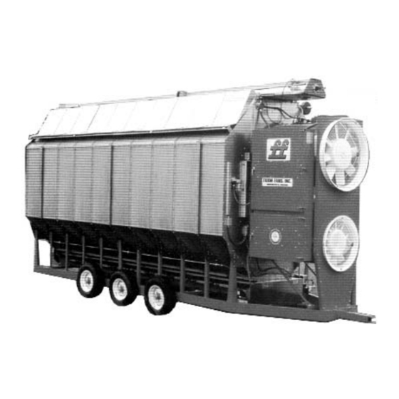
Page 35: Section 6: Dryer Illustrations
Fan-heater access door Main/Safety gas shutoff valve Liquid fuel connection Fig. 6-1 Typical C-2100A Series dryer, LP fuel Main/Safety gas shutoff valve Valve handle (Do not use to close valve. See Section 3 for details.) Indicator Relief valve window Fuel strainer Fig. - Page 36 Pressure gauge Fan-heater control box Gas pressure regulator Liquid solenoid valve Vaporizer adjust- Fuel strainer ment plate (See Section 7 for adjust- ment details.) Fig. 6-3 LP fuel supply components, C-2130 and C-2140 models Flow control valve Hi-Fire solenoid valve (Lo-Fire adjustment) Pressure gauge...
- Page 37 Pressure gauge Hi-Fire solenoid valve Main solenoid valve Burner Hi-Limit thermostat (auto- reset type) Fan-heater access door Manual shutoff valve (use to adjust Hi-Fire gas pressure Fig. 6-5 Typical natural gas fuel supply PL-021 burner control board Ignition transformer 5-amp fuses (partially hidden) Fig.
- Page 38 Fig. 6-7 ASC control panel Fig. 6-8 ASC control panel, internal view...
- Page 39 Fig. 6-9 C-2100A power panel — typical 3-phase model shown...
- Page 40 Retension top and bottom auger drive belts after several hours of Meter roll crossover chain - Adjust to provide 1/4 inch total deflection. operation during initial start-up. Check periodically thereafter. Bottom auger motor Front motor mount bolts - Retighten securely after adjusting belts Belt tension adjusting bolt...
- Page 41 Gearbox SCR drive motor Gearbox drive cover Motor mount adjustment bolt Fig. 6-12 SCR meter roll drive Retension belt drive after first few hours of operation. Check periodically thereafter. Motor mounting bolts - Retighten securely after adjusting belt. Drive belt Fig.
-
Page 42: Section 7: Service
Motor mount bolts - Retighten securely after adjusting chain C-2120A, C-2125A, & C-2130A models: Under normal conditions, replace lubricant after first 250 hours of operation, then change every drying season (or 2500 hours) thereafter using an AGMA #8 gear lubricant. For cold ambient temper- atures conditions (16 N to 50 N F), use AGMA #7 gear lubricant. - Page 43 Fig. 6-16 Grain column cutoff damper decal showing installation Hinged plenum clo- sures - Lifts up to allow easier cleaning Important: Keep inside of dryer clean! Do not allow chaff and other cobustible material to accumulate within air plenum cham- ber.
-
Page 45: Seasonal Inspection And Service
SEASONAL INSPECTION AND SERVICE VAPOCT.DS4 OCTAGONAL The dryer is made of weather resistant construction BURNER and is designed to require a minimum of service; how- ever, we recommend the following items be checked before the unit is used each season. Replace any damaged or questionable parts. -
Page 46: Propane Vaporizer Seasonal Inspection
13. Inspect entire dryer for loose, worn, or damaged parts. If there is contact between the vaporizer pipe and Include check of auger flighting, meter rolls, and other burner or fan housing, adjust the position of the internal parts. Check that temperature sensors within vaporizer to provide clearance. -
Page 47: Burner Control Sequence Of Operation
reduce the vapor temperature. If due to extreme oper- Ignition Transformer, No. 2 Gas Solenoid Valve, and ating conditions it is necessary to further reduce the (LP models only) Liquid Solenoid Gas Valve. Burner vapor temperature, the vaporizer coil may be with- should now fire. - Page 48 sure propeller is removed and installed properly. The from the propeller, especially inside the hub area. (3) recommended procedure is as follows: Carefully inspect the propeller casting for damage, cracks or other defects. Contact the factory if there is any question regarding the structural integrity of the propeller casting.
-
Page 49: Fan Motor Removal And Installation
FAN MOTOR REMOVAL AND 3. Slide propeller over motor shaft and locate it against the motor. INSTALLATION 4. Align the keyway in the bushing with the key and In the event of a motor failure, remove the motor, as SLIDE bushing onto motor shaft. Do not attempt to described, and take it to the nearest authorized service drive the bushing onto the shaft, as it may damage the station. -
Page 50: Heater Removal And Installation
NOTE: Make sure to install and tighten the propeller in C. Disconnect electrical connections to gas solenoid accordance with earlier instructions. valve(s) located within control box. D. Lift pipe tee (with orifice, solenoid valve, and other parts attached) straight up and remove from control box. -
Page 51: Grain And Plenum Temperature Sensor Locations
INTO PLENUM DOORS requires additional lubricant due to leakage or repairs, RTD PLENUM be advised that Farm Fans offers a highly durable, syn- SENSOR thetic oil, FF part no. 069-1132-5 (Mobil SHC634 or equivalent lubricant). Fill to oil level plug (near shaft Fig. -
Page 52: To Clear Jam From Meter Roll
problem is due to some other cause. Check for a break described in Fig. 6-16. Then from outside the dryer, in the power train (broken chain, drive key, clevis pin, open the meter roll access door to remove any foreign coupler, etc.). -
Page 53: Section 8: Wiring Diagrams
Fig. 8-1 C-2100A power circuit — 220V 1-phase... - Page 54 Fig. 8-2 C-2100A power circuit — 220V 3-phase models...
- Page 55 Fig. 8-3 C-2100A power circuit — 440V 3-phase models...
- Page 56 Fig. 8-4 C-2100A general control circuit, p. 1 of 3...
- Page 57 Fig. 8-4 C-2100A general control circuit, p. 2 of 3...
- Page 58 Fig. 8-4 C-2100A general control circuit, p. 3 of 3...
- Page 59 Fig. 8-5 C-2100A burner control circuit circuit...
-
Page 61: Section 9: Troubleshooting
A voltmeter is required for some of the following checkout REFER TO WIRING DIAGRAMS AND PARTS LIST FOR procedures. Before performing any tests, make certain to IDENTIFICATION OF PARTS AND ELECTRICAL TERMI- determine if dryer power supply is 1-phase 230V, 3-phase NALS. - Page 62 TROUBLE CHECKOUT PROCEDURE & INFORMATION - inlet air blocked - fan motor failed b. Backdraft currents during shutdown period. NOTE: In the event the dryer shuts down, the backdraft currents of hot air passing through the housing may cause the burner hi-limit to trip open. •...
- Page 63 TROUBLE CHECKOUT PROCEDURE & INFORMATION Fan motor will not 1. Check that fan circuit breaker and fan switch are ON; also for defective switch or bad wiring connec- tions. start 2. Verify closing of fan motor contactor; check for voltage on load side of contactor and for 120V to contactor coil.
- Page 64 TROUBLE CHECKOUT PROCEDURE & INFORMATION Burner fires - but 1. Wait for several minutes for lock-out device to cool down, then restart the dryer. Immediately after the burner starts operating, connect voltmeter leads across Burner Control Circuit terminal nos. 2 operates only about and T and continue to observe the meter.
-
Page 65: Improper Electronic Temperature Control
TROUBLE CHECKOUT PROCEDURE & INFORMATION Improper Electronic Temperature Control Operation - Zytron Type 1. Low Meter reading with SHORTED SENSOR CIRCUIT - Disconnect appropriate pair of sensor wires from terminal strip. burner(s) staying on Lo- Using a VOM tester, test the sensor leads for approx. 1000 ohms resistance (at 70°F). Also test Fire. - Page 68 Division of ffi Corporation 5900 Elmwood Ave. • Indianapolis, IN 46203 © 1998 ffi Corporation Printed in USA 5-14-98...
Need help?
Do you have a question about the C-2120A and is the answer not in the manual?
Questions and answers