
Related Manuals for LeeLen 8 Series


Summary of Contents for LeeLen 8 Series
- Page 1 Installation Manual V1.0 Xiamen Leelen Technology Co., Ltd. Address: 65 Sunban South Rd., Jimei North Industrial Zone, Xiamen, China Tel.: 0086-592-6157677 Fax: 0086-592-6299688 Website: en.leelen.com...
-
Page 2: Table Of Contents
Contents Foreword ..................................1 1.Construction manual ..............................3 1.1 System overview ............................. 3 1.1.1 Description of digital building intercom system .................. 3 1.1.2 Main functions and features ......................... 3 1.1.3 Topological graph and description of overall system architecture ............3 1.2 Description of cables ............................ - Page 3 3.5.1 Instructions on parameters to be set on the outdoor stations .............. 42 3.5.2 Instructions of parameter settings ...................... 42 3.5.3 Device commissioning steps ......................48 3.6 Instructions on indoor station commissioning ....................48 3.6.1 Necessary parameters to be set of the indoor station ................. 48 3.6.2 Indoor station setting method ......................
-
Page 4: Foreword
Ltd., Leelen Electric Control Technology Co., Ltd, Leelen High Voltage Electric Co., Ltd, SafeHouse Electronic Science and Technology Co., Ltd, and Zhonglin Machine Co., Ltd. It has 37 subsidiary companies, offices and after-sales service sites which are spread all over China. Leelen has an industrial park which covers an area of nearly 110,000m , owns international first-class production and detection equipment and realizes self-production of products through a full set of procedures. - Page 5 Some information about the products in this manual is confidential, and its copyright belongs to Leelen. Leelen reserves the right of final interpretation on all contents of this manual.
-
Page 6: Construction Manual
1.Construction manual 1.1 System overview 1.1.1 Description of digital building intercom system A digital building intercom system is a building intercom and access control system based on computer network transmission. In this system, enclosure station, a center guard unit, a central management computer, outdoor stations, digital access control units, indoor stations, etc. - Page 7 A project usually includes an enclosure access section, a management center section, a building unit access section and an indoor section. The four sections are described in detail below. 1.1.3.1 Enclosure access section For access control of the enclosure, an enclosure outdoor station can be installed. Visitors can call indoor stations or the management center using the enclosure outdoor station to perform the video intercom operation.
-
Page 8: Description Of Cables
1.1.3.3 Building unit access section A unit of a building is usually equipped with a building outdoor station. Visitors use the outdoor station to call building outdoor station of residents in the unit to perform video intercom. Residents can go in and out of the unit by sweeping cards on the outdoor station. -
Page 9: Requirements For Network Cables
station to the magnetic lock L≤10 From the building outdoor RVV2*1.0 12V~24V station to the power supply 3.Main network cable L≤90 From guard unit to the UTP5E 90≤L≤2K central core switch Multi-mode fiber (number of cores, self-defined) L≤20K Single-mode fiber (number of cores, self-defined) L≤90 From... -
Page 10: Requirements For Pipeline Construction
1.2.2.2 Definition of line sequence of crystal heads Note: The line sequence of the RJ45 joints follows the standard 568b, and all manufactured UTP5E wires must pass the UTP5E wire on-off test (a cable wire tester can be used). 1.3 Requirements for pipeline construction For installation and commissioning of the building intercom system, the pre-stage wiring is an important link of the system installation and commissioning. -
Page 11: Requirements For Pipe Material Solution
Requirements for pipe quality: The networked lines among buildings must be independently laid with steel pipes or racks. Requirements for pipe diameter: The inner diameter of the pipes is usually 1.7-2 times the outer diameter of the engineering cable; and the pipes should have as few elbows as possible, better not more than 2. 1.3.2 Requirements for pipe material solution ... -
Page 12: Installation Manual
Wire selection: famous brands are recommended and the channel DC Loop resistance of all selected wires should be less than or equal to 25Ω, which means that the closed loop resistance of any twisted pair is less than or equal to 25Ω. For specific parameters, see electric standards in the "Code for design of comprehensive wiring system project (GB50311-2007).”... -
Page 13: Outdoor Station
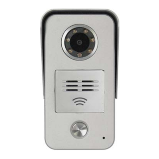
To install screws, directly screw in the screws without inclination or locking may be not tight or the device may be damaged. Installation completed Clean the site and devices. Never clean the intercom devices with flammable cleaners such as alcohol or benzene. - Page 14 Dim(mm):104×214×50 Color: Iron Grey Working Voltage: DC12-24V±10% Max Power Consumption: ≤6W Standby Power Consumption: ≤3W IP Grade: IP54 Capacity of Cards: ≤30,000 pcs Model No.15 Panel Material:Alum Casting series Working Temp: -40℃ to 70℃ Operation: Mechanical Pushbutton Installation: Surface-mounting/emb edded-mounting Dimension(mm):79×148×45 Working Voltage: DC12-24V Max Power Consumption: ≤8W...
-
Page 15: Installation Of Outdoor Station
2.2.2 Installation of outdoor station 2.2.2.1 Model NO.8 outdoor station: Instructions on the installation Embed pipelines and a pre-embedded box. Connect wires, fix the outdoor station and the sealing ring on the pre-embedded box using screws. Place the front panel on the outdoor station. ... - Page 16 Instructions on the insertion installation of the 15-type entrance machine: Embed pipelines and the pre-embedded box. Connect wires, fix the outdoor station on the pre-embedded box with screws. The, then installation is completed. 2.2.2.3 Instructions on the installation of the Model No.10: Instructions of the embedded installation: ...
-
Page 17: Instruction On Device Wiring Interface
2.2.2.4 Instructions on the installation of the Model No.16 outdoor station: Instructions of the embedded: Embed pipelines and the pre-embedded box. Connect wires, place the outdoor station on the pre-embedded box. Fasten the outdoor station and the pre-embedded box with screws. Then, the installation is completed. 2.2.3 Instruction on device wiring interface 2.2.3.1 Wiring interfaces of model No.8 Outdoor Station :... - Page 18 2.2.3.2 Wiring interfaces of model No.15 Outdoor Station:...
- Page 19 2.2.3.3 Wiring interfaces of model No.10/16 Outdoor Stations: Interface description: Power interface: Power input, connected to red/black wires, supporting DC12-24V, supporting SPoE power supply. 12V output: Connected to red/black wires, corresponding implication: 12 V + / GND, output ≤750mA. ...
-
Page 20: Indoor Stations
RS485 interface: Connected to red/black wires, corresponding implication: A /B, externally connected to the access card reader. Signal locking interface: This interface uses a relay to output a switching value, and is connected to orange/yellow/green wires with a corresponding implication of COM / NC / NO; it uses an auxiliary power supply to supply power to the magnetic lock, the negative pole of the auxiliary power supply is connected to the COM terminal of the interface, the NC terminal of the interface is connected to the negative pole of the magnetic lock and the positive pole of the auxiliary power supply is connected to the positive pole of... -
Page 21: Installation Of Indoor Stations
Working Voltage: DC12-24V±10% (SPOE support) Max Power Consumption: ≤5.5W Standby Power Consumption: 1.7W Display: 4.3-inch TFT LCD Operation: Capacitive Touch Installation: Surface Mounting Panel Material: PMMA Dimension(mm): 175×114×15.9 Working Voltage: DC12-24V Max Power Consumption: ≤9 W Standby Power Consumption: 3W Display: 7-inch TFT LCD Operation: Capacitive Touch Installation: Surface Mounting... -
Page 22: Instructions On Device Wiring Interfaces
Instructions on installation steps: Embed pipelines and a pre-embedded box and fix the hanging board with screws. After the lines and the indoor station are connected, the magnet steel on the back of the indoor station is aligned with the convex point on the hanging board, and then the indoor station is hung on the hanging board. - Page 24 2.3.2.2 Wiring interface of V33:...
- Page 25 2.3.2.3 Wiring interface of E60: Description of relevant interfaces of indoor stations Interface Wiring Wiring definition and color Network interface This interface is connected to Connection method of the crystal heads of the power the network distributor/switch cable 586B—586B using a straight-through line. Power interface Red and black wires are Red Black...
-
Page 26: Networking And Intermediate Devices
Power interface: Power input, supports DC12-24V, supports SPOE power supply. Network interface: Network connecting interface, 10/100m self-adaption. Alarm Zone interface: An interface connected to the alarm device. The 7-inch indoor station has 8 zones, and supports the 8th zone as the doorbell. ... - Page 27 Input voltage: AC90V-AC240V/50-60Hz Maximum input power supply: 0.36Amax Output voltage: 24VDC±4V (red + black-) Output current: 2.5A 24V Switch power Static power consumption: 05W supply Working temperature: -40℃ ~55℃; Protective grade: IP30 Appearance size: 169×61×124 (mm) Installation mode: Wall-typed installation Working voltage: 18~24V DC Static power consumption: 05W Working temperature: -25℃...
-
Page 28: Device Installation
Working voltage: 12~24V DC Static power consumption: 0.77W Working temperature: -40℃ ~70℃; Interface: RS485 interface Access card reader Protective grade: IP54 Appearance color: iron gray Panel material: ABS plastic Appearance size: 120×86×19.5 (mm) Installation mode: Wall-typed installation Working voltage: 5V DC Maximum power consumption: 0.82W Working frequency: 13.56MHz... - Page 29 Precautions for installation: Before installation, please read the product manual first, confirm the wiring manner, and confirm that the input voltage is consistent with the product requirements. Please use the power supply within the range of the technical parameters, or the product may be damaged. ...
- Page 30 the screws. Installation completed Installation manner of access card reader Use screws to fix the rear cover on the 86-type pre-embedded box. Fasten the front cover on the back of the rear cover.
- Page 31 Lock the front and rear cover with screws to complete the installation.
-
Page 32: Instructions Of Device Wiring
2.4.3 Instructions of device wiring 2.4.3.1 Wiring diagram of 24V switch power supply: 2.4.3.2 Wiring diagram of digital network distributor:... - Page 33 2.4.3.3 Wiring diagram of access controller:...
- Page 34 2.4.3.4 Wiring diagram of access card reader: Wiring description Digital access Card reader Door state Exit button Power supply Fire alarm Lock control Black White Grey Violet 10-Cor Blue FIRE Green socket Yellow Orange Orange STATE OPEN Brown Access control Black...
-
Page 35: Center Guard Unit (Model No.5)
2.5 Center Guard Unit (model No.5) 2.5.1 Appearances and main parameters Technical parameters: Working voltage: DC12-24V±10% Maximum power consumption: 8W Standby power consumption: <3W Operating system: linux operating system CPU:dual core A7 Main screen: dual core 1.2GHz RAM: 8G Flash:2G Screen: 10.1-inch TFT LCD Resolution: 1280*800 Video format: H.264... -
Page 36: Instructions On Device Wiring
elements of the center guide unit. High Voltage. Danger! Non-professionals may not open the outer casing. 2.5.3 Instructions on device wiring Interface of guard unit Wiring Wiring definition and color Network interface This interface is connected Connection method of the crystal heads of the to the network switch using power cable 586B—586B a straight-through line. -
Page 37: Commissioning Flow
3.2 Commissioning flow 3.3 Parameter planning 3.3.1 Sub-network division Description of sub-network division Before IP planning, check the number of the intercom device that are needed according to actual situations. The IP address is required to be greater than the number of all devices of a residential community because every device... - Page 38 needs an IP address. Simple classification (three types: sub-net masks of A, B and C types of networks can be used.) type IP address and sub-net mask Take 1 9 2 . x xx . x xx . x xx as an example ...
-
Page 39: Planning Of The Call Number Of A Device
192.168.224.1~192.168.255.254 192.168.0.1~192.168.15.254 192.168.16.0~192.168.31.254 4064 255.255.240.0 …… 192.168.224.1~192.168.239.254 192.168.240.1~192.168.255.254 192.168.0.1~192.168.7.254 192.168.8.0~192.168.15.254 2032 255.255.248.0 …… 192.168.240.1~192.168.247.254 192.168.248.1~192.168.255.254 192.168.0.1~192.168.3.254 192.168.4.0~192.168.7.254 1016 255.255.252.0 …… 192.168.248.1~192.168.251.254 192.168.252.1~192.168.255.254 Not recommended! 3.3.2 Planning of the call number of a device 3.3.2.1 Collect information of a residential community information of a residential community includes the quantity of enclosure outdoor stations, quantity of buildings, quantity of ladder ways, floors of each ladder way, number of houses on each floor and quantity of the entrance machines and indoor stations of each house. - Page 40 respectively. 3.3.2.3 Formulate rules for the call number of an outdoor station An outdoor station usually includes enclosure outdoor station and building outdoor station. The call number of an enclosure outdoor station is 8-bit, where the former four bits are usually set to be 8888, and the latter four are usually the sequence number.
-
Page 41: Application Cases
3.3.2.7 Set call modes The call number of a device is a number input by a user to call a certain device. For example, if a user using a certain outdoor station to call an indoor station in room 03 on floor 8 of unit 01 of building 01, it only needs to input the call number (0101-0803) of the outdoor station at the indoor station, and then the user can call the indoor station and perform intercom. - Page 42 Quantity of the enclosure outdoor stations: 2 Quantity of the center guide unit: 1 Formulate IP rules: Select the B-type IP to divide network segments. The network is divided into 16 segments, one of which is selected to set IP. ...
- Page 43 For the serial number of a villa, usually, the unit is set as 1111. A villa can be regarded as one unit with a uniform unit number. For the serial number of the outdoor station of the villa, the 5th digit can be declined from 9 or 8 in turn, and it is ensured that there is no conflict with the numbers of other devices.
-
Page 44: Description Of Commissioning Of Guard Unit
3.4 Description of commissioning of guard unit 3.4.1 Necessary parameters to be set Device address Input "999999" in the engineering setting column to enter the setting interface. Set the device number and IP address of the guard unit. Select defaults for other items. 3.4.2 Parameter setting method Item Setting instructions... -
Page 45: Instructions On Commissioning Of Outdoor Stations
Duty The guard unit can be set on an on-duty state or off-duty state. In the off-duty state, an incoming call is transferred to a guard unit of the next level. Intercom On the intercom interface, you can input the device number using the guard unit to perform intercom. - Page 46 Set the IP address, gateway and subnet mask of the device according to the parameters planned in the project. Network Set the device number, management number, management center number, and outdoor station type of the device according to the planned parameters. Address Check the software version, hardware version, core version, face version, blue-tooth Version...
- Page 47 Set unlocking duration, door state monitoring, opening time limit, and the starting and ending time of the time-limited services. Time limit Dial Set dialing digits.
- Page 48 Set ringtone volume, intercom volume, prompt volume, capture volume, bell volume, etc. Volume Door access Set door access control mode: control by the machine itself or by the digital access control controller.
- Page 49 Set number of the elevator controller and floor of the machine itself. Elevator control Set time and date, and automatically synchronize the time. Date/time Screen saver Set time to enter screen saver mode and screen saver mode.
- Page 50 Set engineering password. Default engineering password is 1234. Password Set language. Language One-key-acquire Press one key to acquire parameters of the device in the configuration software.
-
Page 51: Device Commissioning Steps
Select to re-set to factory default. Reset to factory default 3.5.3 Device commissioning steps Confirm the number of the guard unit. Use the "Security" button of the outdoor station to call the guard unit. The guard uneit confirms if the number of the outdoor station is correct. ... -
Page 52: Indoor Station Setting Method
and input the password "999999" to enter engineering setting: Modify the device number and IP in the address information column (for example, the indoor station of the resident with a home number 0803 can be set as 0101-0803). 3.6.2 Indoor station setting method Item Instructions Remarks... - Page 53 Intercom On the intercom interface, input the 8-digit number of the called party, and then called party can be reached. E.g.: 0101-0803. For monitoring of the outdoor station, set the number of the outdoor station through the video monitoring in the system setting interface, for example, XXXX-XXXX, save the setting and then you can check the outdoor station video through the monitoring list of the indoor station.
- Page 54 1.Zone alarm setting Security Enter the engineering setting interface, click on "Security" to enter the zone setting interface with the following contents: Zone sequence number: wired zones 1-8. Alarm type: Prohibit, permanent, immediate, delay, etc. Sensor types: SOS, smoke, gas, IR, door magnet, etc. Security Click on "Return"...
- Page 55 Home setting: check effective zones in the home mode. Arm delay time: length of time delay from the moment when zones are set to the moment when zones work, for the purpose of preventing arm-and-work situations. Generally, the arm delay time is 60 seconds, with a small allowance.
-
Page 56: Test Steps After Device Parameter Setting
3.6.3 Test steps after device parameter setting Confirm the number of the guard unit. Use the "Security" button of the outdoor station to call the guard unit. The guard unit confirms if the number of the outdoor station is correct. ... - Page 57 Model No.16 outdoor 192.168.1.16 station Indoor station 192.168.1.100 E.g.: (Model No.15 outdoor station) To avoid same with any indoor station, we suggest to set the device No. for No.15 outdoor station as 0101-8803,i.e. the indoor station device No. + 8000 (Note:0803+8000=8803)
-
Page 59: Installation And Commissioning Of Management Software
Modify the parameters needing to be modified in the Web page, and click on "Save." 3.8 Installation and commissioning of management software See the individual User Manual for installation of the management software. 3.9 Commissioning steps of the main platform ...
Need help?
Do you have a question about the 8 Series and is the answer not in the manual?
Questions and answers
Is the doorbell is not working. What can be the reason?