Advertisement
- Data Brochure
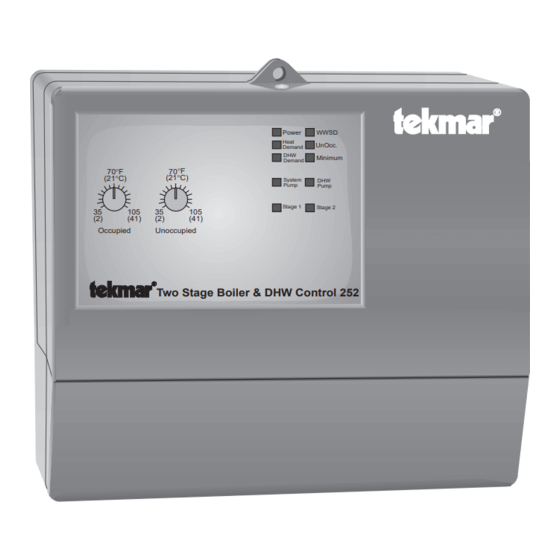
Two Stage Boiler & DHW Control 252
Power
WWSD
Heat
UnOcc.
Demand
DHW
Minimum
Demand
70°F
70°F
(21°C)
(21°C)
System
DHW
Pump
Pump
Stage 1
Stage 2
35
105
35
105
(2)
(41)
(2)
(41)
Occupied
Unoccupied
Two Stage Boiler & DHW Control 252
Heating
24Vac power
is required
supply is on
DHW
is required
System Pump
is on
Occupied
temperature
setting
Unoccupied
temperature
setting
Stage 1 is on
Stage 2 is on
Terminal Plugs:
Power and out-
put connections
Input:
Heat Demand
signal. Optional
Input: DHW Demand
signal. Optional
24Vac power supply
Note: Wiring
is detailed in
Application
Output: Turn on
Brochure
System Pump
A 252
The tekmar Two Stage Boiler & DHW Control 252 is a microprocessor-based control
which regulates the supply water temperature from one or two boilers by turning them
on or off. The supply temperature is based on the outdoor, and optionally, the indoor
air temperatures. When Domestic Hot Water (DHW) is required, the control will operate
the boiler(s) to regulate the supply water temperature in order to satisfy the DHW
requirements.
Outdoor Reset Strategy . . pg. 2
Sequence of Operation . . pg. 3
Installation . . . . . . . . . . . . pg. 4
Settings . . . . . . . . . . . . . . . pg. 7
Control is
maintaining
Minimum Supply
70°F
70°F
(21°C)
(21°C)
35
105
35
105
(2)
(41)
(2)
(41)
Occupied
Unoccupied
Two Stage Boiler & DHW Control 252
Maximum 24 volts
5
6
7
8
9 10
1
2
3
4
Heat
DHW
Power
System
DHW
C
R
Pmp
Pmp
Pmp
Pmp
Dem
Dem
Dem
Dem
Output: Turn on
DHW Pump / Valve
System is in
System is
switched to
Warm Weather
Shut Down
Unoccupied
Power
WWSD
Heat
UnOcc.
Demand
DHW
Minimum
Demand
System
DHW
pump
pump
Stage 1
Stage 2
Date
S/N
11 12
13 14
Stage
Stage
1
1
2
2
Output: Turn
Output: Turn
Input: 2K RTU
on stage #1
on stage #2
Testing . . . . . . . . . . . . pg. 10
Error Messages . . . . . pg. 11
Technical Data . . . . . . pg. 12
Limited Warranty . . . . pg. 12
DHW
pump or valve
Operating Mode
selector switches
is on
Stage
Rotate
DHW during unoccupied
1 2
DHW priority
Auto
DHW valve
Perm. Heat Demand
Zone control
1
2
3
4
5
6
7
8
Indoor sensor
Off
External Heat Demand
DHW pump
2.0
140°F
0.4
3.6
80
200
Heating Curve
DHW
120°F
22°F
80
Off
170
2
42
T est
Minimum
Boiler
Supply
Differential
Power Supply: 24V 60Hz 3VA
1492
Relay capacities: 24V 10A
1234567
No power here
15 16
17 18
19
20 21
22
2K
DHW
Com
UnO
10K
Com
Sup
Out
RTU
Sen
Sen
Sw
Sen
Sen
Sen
Sen
Input:
Unoccupied
signal.
Optional
Input: DHW Sensor
071 Optional
Optional
D 252
10/92
Heating Curve
setting
DHW
temperature
setting
Boiler
Differential
setting
Minimum
Supply setting
Test button &
LED to test
main control
functions
Terminal Plug:
Sensor and
timer inputs
Input: Outdoor
Sensor 070
Included
Input: Universal
Sensor 071. Included
Input:
Indoor Sensor
074 Optional
Advertisement
Table of Contents

Subscribe to Our Youtube Channel
Summary of Contents for Tekmar DHW Control 252
- Page 1 10/92 Two Stage Boiler & DHW Control 252 The tekmar Two Stage Boiler & DHW Control 252 is a microprocessor-based control which regulates the supply water temperature from one or two boilers by turning them on or off. The supply temperature is based on the outdoor, and optionally, the indoor...
- Page 2 A very warm room temperature can shift the curve far enough down to put the control into WWSD at cool outdoor temperatures. Refer to the tekmar Essays E 001 and E 002 for more detailed information regarding control strategy and integration of control functions.
-
Page 3: Sequence Of Operation
Sequence of Operation When the Two Stage Boiler & DHW Control 252 is powered-up, the "Power" light will come on and the control will cycle through an automatic test routine described in detail on pages 10 and 11 of this brochure. When the test routine is completed and no errors are detected, the control exits the test routine and enters the operating mode. -
Page 4: Dhw Operation
Check the contents of this package. If any of the contents listed are missing or damaged, please refer to the Limited Warranty and Product Return Procedure on the back of this brochure and contact your wholesaler or tekmar sales agent for assistance. - Page 5 Standard 18 to 22 AWG solid wire is recommended for all low voltage wiring to tekmar controls. Heavier guage wire may not fit properly into the terminal plugs, while lighter guage wire is too fragile and may also contribute too much resistance to the circuit.
- Page 6 (1) Connect the two wires from an Indoor Sensor 074 or a tekmar 10K Zone Control to terminals 10K Sen — Com Sen (19 and 20). (2) Connect the two wires from a tekmar 2K RTU, (305, 307, 308, or 310) or a tekmar 240 Zone Control to terminals 2K RTU — Com Sen (15 and 17).
- Page 7 For specific application details refer to Application Brochure A 252. A more detailed technical description of the effect of control settings on overall system operation is described in the tekmar Essay E 002. Heat Demand switch...
- Page 8 Zone Control/Indoor Sensor switch When this selector switch is in the "Indoor Sensor" position, and a tekmar Indoor Sensor 074 or a tekmar 2K RTU is connected, the control receives room temperature feedback from the RTU or Indoor Sensor and the...
- Page 9 Minimum Supply Temperature This dial should be set according to the requirements specified by the (99) 3.6 3.0 2.4 2.0 120°F boiler manufacturer. Many boilers require a minimum operating Heating (88) temperature to prevent corrosion from flue gas condensation. The Curve control raises the supply temperature to the Minimum setting when the Minimum Supply...
- Page 10 Operational test of control functions - Test button The Two Stage Boiler & DHW Control 252 has a Test button which can be used to test all of the main control functions at any time. When the control is initially powered-up, or when the Test button is pushed, the control automatically runs through the following test procedure.
-
Page 11: Error Messages
Step Eight Troubleshooting As in any troubleshooting procedure, it is important to isolate a problem as much as possible before proceeding. The Error Messages and the Test button greatly simplify troubleshooting of the 252. If a fault occurs during operating mode or during the test routine and the control is flashing an Error Message, identify the fault from the look-up table at the bottom of this page and then follow standard testing procedures to confirm the problem. -
Page 12: Technical Data
This limited Return Goods Authorisation (RGA) number from tekmar. warranty covers the cost of parts and labour provided by tekmar to correct Please include the following information with the product: The full address of the defects in materials and/or workmanship.
Need help?
Do you have a question about the DHW Control 252 and is the answer not in the manual?
Questions and answers