
Summary of Contents for CORNING Ascent 6970
- Page 1 ® ™ Corning Ascent Fixed Bed Reactor Process Development System Instruction Manual Catalog Number: 6970...
-
Page 2: Table Of Contents
Table of Contents 1.0 Safety ................ 1 6.0 Process Overview ........... 19 1.1 Personal Protective Equipment (PPE)......... 1 6.1 System Set Up ................20 1.2 Equipment Safety ..............1 6.1.1 Initialization ..............21 6.1.2 Media Fill and Prime Phase ........21 2.0 Introduction ............. 2 6.1.3 Media Conditioning Phase ........21 3.0 Site Requirements ........... - Page 3 7.7 Calibration ................37 8.0 Protocols ..............64 7.8 Equipment Control Faceplates ..........38 8.1 Pump Calibration ..............66 7.8.1 Equipment Parameter Control Faceplates ...39 8.2 Media Phases .................68 7.8.2 Equipment Totalizer Faceplate .......40 8.2.1 Initialize Phase ............68 7.8.3 Proportional, Integral, Derivative (PID) Loop 8.2.2 Media Fill and Prime Phase ........76 Faceplate ..............40 8.2.3 Media Conditioning Phase ........79...
- Page 4 9.0 Preventative Maintenance ........112 Appendix 1. PID Loop Calculations and ....117 Tuning Guidance 9.1 Recommended List ............112 Appendix 2: Phase Permissive ........118 9.2 Routine Screen Cleaning ..........112 Appendix 3: Operational Sequence Reference ..119 9.3 Gas Filter Replacement Procedure ......... 113 Tables 9.4 Enclosure Filter Replacement..........
-
Page 5: Safety
1.0 Safety This section describes how to safely set up and use the Corning® Ascent™ Fixed Bed Reactor Process Development (FBR PD) System. 1.1 Personal Protective Equipment (PPE) Non-toxic media is handled during seeding and harvest. Basic PPE shall include: •... -
Page 6: Introduction
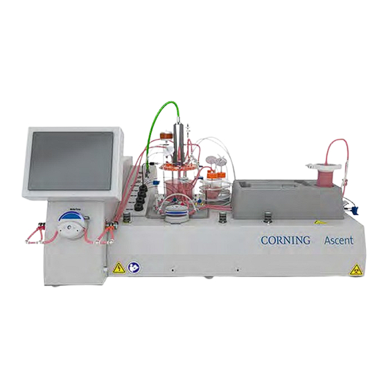
2.0 Introduction The Corning® Ascent™ FBR PD System consists of a system controller and single-use, pre-sterilized components including a bioreactor, a Media Conditioning Vessel (MCV), and other consumables, such as tubing, connectors, probes, in-line sensors, and bottles (Figure 2-1 and Figure 2-2). -
Page 7: Site Requirements
Section 5.1.1 Bar code scanner Section 5.6 3.0 Site Requirements Table 3-1 lists the site requirements to set up the Corning® Ascent™ FBR PD instrument. Table 3-1. Site requirements. Type Description Operating Conditions The instrument is designed for use under standard operating conditions per UL 61010-1 where: •... -
Page 8: Set Up And Installation
This section describes how to connect and power up the Corning® Ascent™ FBR instrument. 4.1 Power, Air, and Gas Connections The Corning Ascent FBR is a benchtop instrument with accessible connection ports to main power, air, O , CO , and N (Figure 4-1). -
Page 9: Instrument Overview
5.0 Instrument Overview This section describes the Corning® Ascent™ FBR instrument, which includes the pre-sterilized consumables and the system controller. 5.1 Pre-sterilized Consumables Table 5-1 is a list of the pre-sterilized, single-use consumables that shall be properly discarded as biohazardous waste, as mandated by local and state laws. - Page 10 Figure 5-2 shows the MCV headplate connections, tubing lines, and ports. Figure 5-2. MCV headplate connections for media maintenance, transfection, inoculation, and media sampling (see Table 5-2). Table 5-2. Tubing and ports on the MCV headplate. Label Description Not used. Adds and removes media from the MCV.
-
Page 11: Sensor Tray
Inside the MCV are the following (Figure 5-3): • An agitator shaft with a rotating 6-blade Rushton impeller that facilitates homogenous media mixing • A dip tube connected to the gas/sparging line • A dip tube for media addition, media removal, and media return •... -
Page 12: Inoculum, Base, And Feed Bottles
5.1.5 FBR with Sterile Connectors The Corning® Ascent™ FBR system has two options to connect media flow from the MCV to the FBR and return media from the FBR to MCV. Option A uses Lynx® connectors while Option B uses AseptiQuik® G connectors (Figure 5-6 and Figure 5-7). At experiment start, the sterile connectors (Option A or B), are connected to their mating sterile connectors on the MCV. -
Page 13: Harvest Kit
5.1.6 Harvest Kit The Corning® Ascent™ FBR system has a consumable harvest kit in a portable tray for easy positioning enabling users to recover cells from the bioreactor (Figure 5-10). Prior to harvest, the bioreactor is fluidically isolated from the MCV by clamping the recirculation inlet, and the outlet tubing. During the Harvest Phase, the recirculation pump, in conjunction with the automated pinch valves, perfuse harvesting solutions from the harvest kit through the bioreactor. - Page 14 Table 5-4. Harvest kit. Label Bottle/Vessel Description Harvest Collection This bottle is used to collect cells harvested from the bioreactor. During the harvest step, harvest solution flushes out the cells from the bioreactor, and the cells suspension is collected in the collection bottle. Harvest Solution This bottle contains harvest solution such as Accutase®...
-
Page 15: Sterile Connectors
5.1.7 Sterile Connectors Table 5-5 and Table 5-6 list the sterile connectors used at cell culture and harvest. Table 5-5. Sterile connections at Media fill, Prime, and Conditioning set up. Lynx® CDR AseptiQuik® G AseptiQuik® S Connector AQG17004 AQS17002 Connection Purpose MCV to bioreactor recirculation line Media perfusion... -
Page 16: Agitator Motor
Table 5-7. Interface panel ports. Label Interface Panel Description Reference Agitator motor Agitator motor cable Section 5.2.1 Filter heater Exhaust filter heater connection Section 5.2.2 MCV pressure In-line sensor that monitors pressure on the MCV gas vent Section 5.2.3 MCV sparge Sparging gas line in the MCV Section 5.2.4 MCV temperature... -
Page 17: Pressure Sensor
5.2.3 Pressure Sensor Located below the exhaust filter is the MCV pressure sensor (Figure 5-16). It is designed to detect a low or high-pressure event within the MCV that can occur (e.g., if the vent filter clogs because of condensate build-up or foam entry into the exhaust filter). The sensor relays the high-pressure event to the controller. -
Page 18: Mcv And Fbr Dissolved Oxygen (Do) Sensors
5.3 Pumps The Corning® Ascent™ FBR system utilizes four peristaltic pumps programmed to perform a specific range of operations (Figure 5-22). The two large pump heads (Figure 5-23) are used for media fill and recirculation, while the two smaller pump heads (Figure 5-24) are used for automating feed and base additions. -
Page 19: Pinch Valves
Figure 5-23. The recirculation pump uses robust tubing to withstand continuous pumping. Figure 5-22. Peristaltic pump locations. Refer to Table 5-8 for descriptions. Figure 5-24. Base and feed pumps have color-coded covers to match the colored clips on the tubing lines. Table 5-8. -
Page 20: Pinch Valve Positions
Figure 5-26. A pinch valve close-up. The cover label shows where to align and load the tube lines based on the tubing clip color. Figure 5-25. Pinch valve locations. Refer to Table 5-9 for descriptions. NOTE: The white tubing clip is always positioned next to the instrument, while the black tubing clip is on the outside. 5.4.1 Pinch Valve Positions Valve positions are important for directing tubing flow when the system calls for it. -
Page 21: Mcv And Fbr Heaters
Table 5-9. Pinch valve colors and positions for tubing load. The valve position channels tubing flow to a specific bottle. Valve Position Image Description Bottom The red and orange pinch valves perform the following: Media Waste Media Addition bottle bottle •... -
Page 22: Fbr In-Line Heater And Temperature Sensor
A 2D bar code scanner (Figure 2-2) is used to scan the bar coded consumables. While the scanner accepts most bar codes and QR formats, only certain Corning consumables listed below are recognized and the data automatically populates the Bar Code name field in the Bar Code Input pop-up window (see Section: 7.11.1, Figure 7.53). -
Page 23: Process Overview
6.0 Process Overview The Corning® Ascent™ System processes are grouped into three categories: (1) System set up which includes Media Fill/Prime, Media Conditioning, and Sensor Calibration; (2) Cell Culture; and (3) Harvest. This section details the Sequence Phases and Auxiliary Phases in each category (Figure 6-1). -
Page 24: System Set Up
Table 6-1. Phases run frequency and conditions. Run Frequency Phase Constraints Once Initialize Cannot be cancelled. Media Fill/Prime Cannot run after Harvest Preparation while a Harvest Phase is active. Media Conditioning Cannot run after Harvest Preparation while a Harvest Phase is active. Inoculation Cannot run after Harvest Preparation while a Harvest Phase is active. -
Page 25: Initialization
6.1.1 Initialization The user defines the batch ID and selects batch parameters by entering user-defined values and scanning consumables to populate applicable setpoints. Pumps may be calibrated prior to or during Initialization, and the pressure sensor is zeroed out prior to introducing liquids, and starting pumps or gas flows. -
Page 26: Cell Culture
6.2 Cell Culture This section describes all sequences during cell culture which is a subset of Media Phases. 6.2.1 Media Maintenance Media is maintained at user-specified setpoints. The system automatically controls each loop to the setpoints upon starting this phase and overrides previous loop settings entered in either Manual or Operator mode. -
Page 27: Transfection
6.2.4 Transfection Transfection complex is added to the Media Conditioning Vessel. Table 6-8 shows the setpoints controlled. The system stops the recirculation and control loops for transfection and runs at the agitator setpoint. Once the transfection reagent addition into the MCV is complete, it is mixed in the MCV for a specific duration. -
Page 28: Media Removal
6.3.4 Media Removal This phase removes the specified media volume from the MCV one time per operation. Table 6-12 shows the setpoints controlled. Table 6-12. Media removal setpoints. Setpoints Media Pump Flow Media Removal Volume 6.3.5 Perfusion or Media Replacement This phase removes spent media first and then adds the same volume (the Totalizer Volume) to the system for a specific number of cycles at user-defined instances. -
Page 29: Harvest Preparation
6.4.1 Harvest Preparation Prior to harvest, the harvest kit bar codes are scanned, and all control loops (temperature, DO, and pH) are turned off. The bioreactor inlet and return lines are manually clamped to fluidically isolate the bioreactor from the MCV. The MCV tubing is removed from the recirculation pump, and replaced with the harvest pump tubing. -
Page 30: Cell Removal
Figure 6-5. Cell release path highlighted. 6.4.4 Cell Removal This phase transports the released cells and solution from the flush bottle through the bioreactor and into the collection bottle by pressurizing the system via the pressure control valve inside the instrument. Air pressure can be set at approximately 10 to 15 psi. The specified air pressure is first applied to the flush bottle during Pressurization Delay allowing time to build up pressure. -
Page 31: Final Rinse
6.4.5 Final Rinse This phase takes place right before the final Cell Removal Phase to transport any material remaining in the flush bottle to the harvest solution bottle by pumping extra wash solution through the bioreactor into the flush bottle. A final cell removal cycle takes place after the final rinse to collect the remaining cells in the collection bottle. - Page 32 Table 7-1. Main screen overview. Label Navigation Buttons and Status Indicators Reference Password login access screen. Section 7.3 There are separate screens for Cell Culture Overview and Harvest Figure 7-1 Overview. Each screen shows the equipment modules for process Figure 7-2 control.
- Page 33 Table 7-2. Display symbols and colors. Illustration Symbol Description Meaning Process status indicators Flashing green reset button Abort reset is required. Flashing green prompt box Prompt is active. and an ‘i’ in a red circle Red ‘Aborted’ button Abort is active. Colored border around pinch Does not require user attention.
- Page 34 Illustration Symbol Description Meaning Device status symbols White flag Device is in Operator mode. Pointing finger Device is in Manual mode (MCV DO, FBR DO, MCV pH, MCV Temp, FBR Temp). TV remote Device is in Auto mode (MCV DO, FBR DO, MCV pH, MCV Temp, FBR Temp). Black octagon Device is interlocked.
-
Page 35: Access Levels And User Modes
7.3 Access Levels and User Modes Corning® Ascent™ FBR system has three access levels: Default, Operator, and Engineer. When entering the username and password, a keyboard will pop up (Figure 7-3). Table 7-3 shows the access at each user level. -
Page 36: System Screen
7.4 System Screen Selecting the Sys button next to the date and time field will show the software information screen (Figure 7-4). The system ID name in the field is displayed on each HMI screen. There are four options on the Sys window: Clean Screen, Time and Date, Shutdown User interface, and Password Admin. -
Page 37: Phase Status, Abort, And Global Reset
Figure 7-7. Password Admin. The passwords for the Operator and Engineer users can be changed from the “Password Admin” button located within the System Information faceplate. Only the Engineer user access levels can select this button. When Password Admin button is selected, the user has the following four options: •... -
Page 38: Media, Harvest, And Auxiliary Phases
Table 7-5. Flashing green button and prompt window. Label Description A message header reminding users to complete an action, or to confirm a completed step. Press X to close the prompt window. This allows users to complete the required tasks prior to acknowledging the prompt. Data entry details. - Page 39 Figure 7-10. Media Phases. Inoculation is highlighted as an example to show the phase set up pop-up. Table 7-6. Media Phases descriptions. Media Phases Navigation Buttons and Status Indicators Initialize Resets the system in preparation for the next experiment. Starts the batch timer, enters batch name, prompts to scan bar code on the consumables, reminds to calibrate pumps and load MCV and FBR consumables.
- Page 40 Table 7-7. Harvest Phases descriptions. Harvest Phases Description Harvest Preparation All loops – heaters, DO and pH – are turned off. Preparation time to connect Harvest kit to the bioreactor and fluidically isolate the bioreactor. Harvest Preparation can only be performed once. Harvest Wash The bioreactor is washed with DPBS buffer at a user-specified flow rate.
-
Page 41: Navigating Sequence And Auxiliary Phase Faceplates
7.6.1 Navigating Sequence and Auxiliary Phase Faceplates To run a sequence, the user selects the play symbol. When the Sequence Phase is started, the button becomes an X and a green Running title indicates that the phase is active. Should the user trigger an Auxiliary Phase to run during an active Media Phase or Auxiliary Phase, the system places the current phase on Hold, as indicated on the faceplate, which allows the newly triggered Auxiliary Phase to run. -
Page 42: Equipment Control Faceplates
Likewise, in-line sensor probes can be calibrated via Probe Calibration (Figure 7-15). DO and pH probe values are bar coded into the system. The user either verifies the bar coded values or manually enters values from the data sheet during Media Conditioning (see Section 8.2.3.1. -
Page 43: Equipment Parameter Control Faceplates
Figure 7-16. Changing the base pump setpoints and the accompanying pop-up screens. 7.8.1 Equipment Parameter Control Faceplates Selecting an equipment component (e.g., pinch valve), will create a pop-up with the corresponding tag name, current state, setpoint, actual value, and command options. Figure 7-17 shows all equipment faceplates that allow control access options listed in Table 7-9. Figure 7-17. -
Page 44: Equipment Totalizer Faceplate
7.8.2 Equipment Totalizer Faceplate Pressing any totalizer field provides access to change the reset the totalized value and start/stop the totalizing function. (Figure 7-18). The mass flow controllers, base, feed, and media pumps have totalizers for tracking gas and liquid delivery. NOTE: Displayed totalizers for the media, base and feed pumps, and the MFCs are reset and restarted during the Initialize Phase. - Page 45 Figure 7-21 shows the alarm limits and loop configuration screen. Fields with asterisks are preconfigured and should only be modified under Corning’s advisement. Figure 7-21. PID Configuration window for alarms and loop tuning. Figure 7-22 is the PID tuning graphic used to monitor loop parameters during PID tuning.
-
Page 46: Control Loop Setup
Figure 7-24 is the PID auto-tuning window. This is a standard function supplied with the PID control loops. This functionality shall be used by a training controls engineer familiar with the Rockwell PID auto-tuner. NOTE: Corning cannot guarantee the performance of this function nor the response of the system. Figure 7-24. Graphing tuning window and auto-tune window. -
Page 47: Mcv Do Control Loop
Figure 7-26. MCV DO Control Loop Configuration example values when all parameters are changing with DO demand. Figure 7-27. MCV DO Control Loop Configuration example values when each parameter is cascaded stepwise. Figure 7-28. MCV DO Control Loop Configuration example values when gas flow is held constant. -
Page 48: Mcv Ph Control
Figure 7-30. Example of MCV DO control configuration table when the system is connected to four gases (air, oxygen, nitrogen and CO While using this configuration, the user would be able to maintain MCV DO level as low as 24% (5% oxygen concentration in purging gas mixture). - Page 49 Figure 7-32. Split Range (A) and Deadband Control (B) illustrations. pH Deadband The pH control loop utilizes a deadband around the setpoint. The setpoint deadband upper and lower limits are configurable. The system does not allow for entries wherein the upper limit is lower than the lower limit or vice versa. See Deadband Control in Figure 7-32B. Region A shows when the pH is higher than the lower deadband limit and lower than the upper deadband limit, the Controller Value is set and held at 50%.
-
Page 50: Bioreactor Do Control
7.9.3 Bioreactor DO Control Bioreactor DO control is accessed via the FBR DO Control setup faceplate (Figure 7-33). The DO at the bioreactor output is controlled by the recirculation pump speed. When the bioreactor DO drops down to the setpoint, the bioreactor DO control loop will begin increasing the pump speed from the minimum specified value to up to the maximum value (Figure 7-34). -
Page 51: Create A New Time Period
Figure 7-36. Trends Toolbar Symbols (see Table 7-14). Table 7-14. Trends symbol description. Label Description Label Description Save new trend file Stack Tag Y-axes. Shows all traces simultaneously on the chart, each with its own scaled stacked along the Y-axis. Print current trend screen Single Trace. -
Page 52: Tag List Features
Figure 7-37. Grayed-out versus not-grayed-out time bar. The steps for creating a new time period are: 1. Toggle off Live Refresh mode to select an absolute time period. 2. In the toolbar, select New Time Period. The Time Bar changes color from blue to red to indicate a new time period creation is active. •... -
Page 53: Display Trace
Figure 7-40. Tag list properties. Above the tag list is a blue pane that when clicked, drags the tag list up or down, and adjusts the tag list view size. To collapse the tag list view (Figure 7-39), click on the middle of the blue pane along the dotted lines (Figure 7-41). Figure 7-41. - Page 54 Where the X-axis cursor is placed, the values for all displayed tags are shown next to the cursor (Figure 7-43). Figure 7-43. X-axis cursors and displayed tag values. Likewise, when the Y-axes cursor button is selected, two horizontal lines are generated on the chart area that can be moved along the Y-axis (Figure 7-44).
-
Page 55: Templates
7.10.4 Templates The system comes preloaded with five default templates (Table 7-16). The Template function allows users to customize templates by selecting/adding parameters or to select default templates with selected parameters. Templates are stored in the database for user selection or for future customization. Table 7-16. -
Page 56: Save Changes To Existing Template
7.10.4.3 Save Changes to Existing Template 1. After making changes to an existing template, press Save Template from the toolbar. 2. The user can either select the template they would like to overwrite or enter the same name as the template file they wish to overwrite. - Page 57 3. Select the green plus button in the lower left-hand corner of the dialog box (Figure 7-48). Figure 7-48. Select the green plus button. 4. Select the small plus (+) button next to Data Logs, then select FTDatalog (Figure 7-49). Figure 7-49.
-
Page 58: Remove Template Tags
5. Select the desired tag to be added from the list at the bottom of the dialog box. Once a tag is selected, select OK to complete. This may be repeated to add all desired tags (Figure 7-50). Figure 7-50. Pick desired tag from Items box. Press OK to finish adding tag. -
Page 59: Trend Properties
7.10.4.7 Trend Properties Trend Properties allow users complete control over the trend page. NOTE: Trend data is currently deleted whenever the system is powered off. Data is saved when the user leaves the page, and will show continuous run data from when the machine was powered on. Figure 7-51. -
Page 60: Data File Entry
The Raw Barcode contains the data as read by the bar code reader or entered by the user manually. The Barcode Name represents the name generated by the bar code reader for specially recognized Corning consumables sets (see Section 5.6 Bar Code Scanner). The subsequent columns contain individual data values read from the special Corning consumables sets such as pH and DO calibration coefficients, the bioreactor surface area and recirculation loop volume. -
Page 61: Usb Save
Figure 7-56. Pop-up window to enter data. 7.11.3 Recirculation Volume Recirculation volume refers to the media volume in the entire FBR consumables recirculation loop. The BRX Loop Volume pop-up box is automatically populated when users scan the bioreactor consumable bar codes If welding on/off additional tubing into recirculation loop happens, then user shall update and modify the BRX Loop Volume field (Figure 7-57). -
Page 62: Diagnostics
7.12 Diagnostics The Diagnostics screen lists various system activities (Figure 7-59) and is used for troubleshooting when requesting for vendor support (for example, anytime a faceplate is opened or closed, anytime someone logs in or out, and errors from the communication network). Selecting one of the displayed messages provides details in the grey area below. -
Page 63: Remote Access
3. Select the desired local computer folder based on the folders mapped on the machine that launched TightVNC. 4. Using the double left arrow button, move the file from remote to a local folder. Figure 7-63. Select the highlighted Corning® Ascent™ remote folder. -
Page 64: Alarms
Figure 7-64. TightVNC file transfer steps. 7.14 Alarms Alarms indicate that the operating system has fallen outside of the acceptable programmed range. In the event of an alarm condition, the affected variable tag name will flash in the appropriate color in its control faceplate. Pressing the bell symbol (Figure 7-65) at the bottom of the main screen opens the alarm history which is accessible at Operator and Engineer levels. - Page 65 Table 7-20. Alarm type. Alarm Alarm Event How to Clear Pressure sensor exceeds Pressure HI/LO All mass flow controllers go to zero and the User is prompted that phase will resume Alarm setpoint. isolation valve inside the instrument closes. when MCV pressure returns to normal. The current phase moves to Hold.
-
Page 66: Alarm Interlocks
Analog alarms can be edited from the analog signal faceplate by selecting the Maintenance (wrench) icon when in Engineering mode (Figure 7-68). NOTE: Alarm limits have been set up according to equipment or process related limits and should not be adjusted without consultation with Corning. Figure 7-68. Analog Alarm Limit Viewing. 7.14.1 No-Alarm Interlocks The system has automated interlocks described as follows: •... -
Page 67: Power Loss And Recovery
Table 7-21. Equipment module interlock list. Equipment Module (EM) Interlock Conditions All EMs Recirculation pump is off for 30 seconds When Global Abort is initiated MCV Temperature EM After agitator is off for 30 seconds Any MCV heater fault is active MCV temperature sensor failed or is out-of-range MCV temperature sensor is disconnected MCV temperature HIHI alarm is active... -
Page 68: Protocols
8.0 Protocols The Corning® Ascent™ FBR system provides users the flexibility to customize experiments. Users select the programmed Sequences under Media, Harvest and/or Auxiliary Phases to achieve their experiment needs. Media Phases can run after a Harvest Preparation Phase but not during an active Harvest Phase. - Page 69 Protocols that ensure system integrity are found in Table 8-2. Table 8-2. Calibration protocols. Protocol Reference Pump Calibration Section 8.1 Sensor Calibration Section 8.2.3.1 Reminder 1: If the green button with an exclamation mark is flashing green, press to view, and address the task in the prompt window. Press after the manual task is completed to resume (Figure 8-2).
-
Page 70: Pump Calibration
Figure 8-5. Clamp unused connections with Figure 8-6. Tubing must be centered between AseptiQuik® connectors. V-groove clamp in pumps. 8.1 Pump Calibration This procedure calibrates the 4 pumps, recirculation, media, feed and base pumps, offline using the calibration tubing listed in Table 8-3. Calibration tubing is part of the consumables set. - Page 71 4. Prime the calibration tubing with water first. Press the appropriate pump icon on the HMI. 5. A pop-up faceplate will appear. Follow the steps below: 1. Press Operator. A second pop-up screen will appear. 2. Press the Operator icon. 3.
-
Page 72: Media Phases
9. Once the duration is complete, measure the volume collected by either volume or mass. Enter the results into the Amount Collected. Press Complete Calibration. NOTE: If a fault occurs or pop-up is closed and calibration is not complete, the pump may not operate properly in process. - Page 73 4. Confirm pump calibration. • A prompt will remind the user to perform pump calibration (see Section 8.1). • Press to acknowledge. • The system activates BatchData and ProcessData files after the user confirms pump calibration. 5. Scan the bar code on the sterile bags containing the MCV and FBR consumables. •...
- Page 74 9. Install the agitator motor. • Align the two slots on the agitator motor magnetic coupling housing with the two tabs on top of the MCV impeller post to mount the agitator motor. 10. Connect the MCV pressure sensor and MCV sparge line. Plug in the MCV pressure sensor and MCV sparge line to the interface panel.
- Page 75 15. Connect the sensor tray in-line sensors. • Tilt the sensor sideways prior to install to prevent air bubbles. • Loosen each colored cap on the sensor tray. • Insert the in-line sensor probe from the interface panel to the color matched sensors on the sensor tray.
- Page 76 18. Place the bioreactor tray over the nest. • Place the tray over the sterile connectors in the FBR nest. • If using Lynx® connectors, check that they are still seated correctly in the brackets. If using AseptiQuik® G connectors, check that the tubing is underneath the FBR nest to maximize heat transfer.
- Page 77 23. Orange and red pinch valves check. • Press the flashing green status box for the next prompt. • Select Yes to check the orange and red pinch valves actuation. • Visually check each pinch valve covers. The pinch valve cover should visibly depress and extend during actuation.
- Page 78 3. Remove the protective covers on both the MCV and bioreactor Lynx® connectors 4. Orient the faceplates in the same direction. 5. Mate the male and female faceplates. Push together until the top clip is engaged. 6. Slide the blue door away from the sterile housing to a locked position. 7.
- Page 79 9. Place the connected Lynx® connector on the bracket in the bioreactor nest, with the recirculation line Lynx® connector closest to the user. Repeat the process to connect the media return line Lynx® connectors, and place the return media line Lynx® connector in the bracket farthest from the user. 10.
-
Page 80: Media Fill And Prime Phase
4. Orient to match both AseptiQuik® connectors on the connecting lines. 5. Tightly press both AseptiQuik® connectors to an audible click. TIP: When properly mated, the latches at each end on the connector set flush. 6. Grip and pull out the tabs to remove the connector membranes. 7. - Page 81 2. Connect the media addition line. • Flip open the AseptiQuik® connector blue tab on the media addition line and media addition bottle line. • Follow procedure in Section 8.2.1.2. • Release the white plastic clamp on the media addition line so that it is open. •...
- Page 82 4. Confirm current MCV volume. • If Media Fill Volume differs from Fill Volume Remaining, enter actual MCV volume in MCV Vol. Adjustment. • Enter the new value and close window (press X) when done. NOTE: Pressing Zero will zero the MCV level. 5.
-
Page 83: Media Conditioning Phase
This illustration shows an example of MCV media flow to the Lynx® connector before perfusing the bioreactor. 8. Media perfusion. • This illustration shows the bioreactor perfused with media (from the inlet at the base). • Media flow continues up along the bioreactor outlet to the return media tubing. 9. -
Page 84: Sensor Calibration
2. Values from a previous run will populate the setpoints: • Agitator Setpoint • Recirculation Pump Setpoint • MCV TIC Setpoint • BRX TIC Setpoint • Air MFC Flow Rate • O MFC Flow Rate • CO MFC Flow Rate •... -
Page 85: Media Maintenance Phase
3. pH sensor calibration. • Take a media sample and measure pH level offline. • Enter the new pH Reference value. • Press Span Set next to pH Reference value. • The pH reading should now equal the new pH Reference value from the drawn media sample 4. -
Page 86: Inoculation Phase
2. Enter setpoints: MCV TIC (Temp.) Setpoint • 30°C to 42°C, typically 35°C to 42°C BRX TIC (Temp.) Setpoint • 30°C to 40°C, typically 35°C to 42°C MCV DO Setpoint • 100% to 200%, typically 100% NOTE: For Low-DO (4-Gas) operation with the proper MCV DO Loop Configuration, this can be set as low as 0% (refer to Section 7.9.1.1). - Page 87 Enter setpoints: • Cell Attachment Flow Rate (the recirculation pump flow rate for seeding/attachment) • Inoculation Seeding Volume (inoculant volume) • Cell Attachment Duration • Recirculation Pump Ramp Time (time to ramp to the Automatic control setpoint after Cell Attachment Duration is complete is typically the minimum flow rate set in the BRX DO Control menu).
-
Page 88: Mcv Inoculation (Preferred Option)
6. Transition to previous phase. • When Cell Attachment Time is complete, the recirculation pump returns to the bioreactor DO controller minimum flow rate. NOTE: The time to ramp is set by the Ramp Time setpoint. • The recirculation pump ramps down to BRX DO Min. setpoint (stepwise ramp, every 5 sec.) 7. -
Page 89: Fbr Inoculation
3. Use the positive pressure displacement bulb to feed the solution into the MCV. The system begins auto-sequence steps. Return to Section 8.2.5 to sample the media. 8.2.5.2 FBR Inoculation While FBR inoculation is a programmed option, MCV inoculation is the preferred method. 1. - Page 90 3. Prime inoculation line. • Follow prompt and jog the recirculation pump in reverse to prime the inoculation line. • Stop the recirculation pump after the inoculation line is primed. 4. Inoculum addition. Follow prompt to begin inoculum addition by jogging the recirculation pump forward to inject inoculum into the recirculation line.
-
Page 91: Adding Base
8.2.5.3 Adding Base After inoculation, an alkaline like Sodium Bicarbonate or Sodium Hydroxide, may be automatically added to the MCV to maintain pH. This procedure shows how to connect the Base Bottle to automatically add the base solution to the MCV. NOTE: Both the Base and Feed pumps only run in one direction, counterclockwise, to advance flow to the MCV. - Page 92 Enter setpoints: - Media Pump Removal Flow Rate (mL/min.) - Media Pump Removal Volume (mL) - Media Pump Addition Flow Rate (mL/min.) - Media Pump Addition Volume (mL) - Recirc. Pump Addition Flow Rate (mL/min.) - Minimum MCV Volume (mL) - Stabilization Duration (min.) Press ...
-
Page 93: Transfection Phase (Process-Dependent)
7. Once the user confirms that the MCV Volume is correct, Stabilization Duration begins 8. A prompt to confirm that Media Exchange phase is complete will display. Press to acknowledge that Media Exchange Phase is complete. 8.2.7 Transfection Phase (Process-dependent) This procedure shows how to add transfection complex to the MCV via one of the two AseptiQuik®... -
Page 94: Transfection (Using Feed Pump)
5. If the user is manually adding transfection complex to the MCV, continue to the next step. If the user is using the feed pump to add transfection, go to Section 8.2.8. 6. A prompt will remind the user to begin injecting the transfection complex into the MCV. Press ... -
Page 95: Auxiliary Phases
3. The feed pump is automatically switched to Operator mode. Open the pump menu and enter the flow rate, and start pump to inject the reagent into the MCV. 4. Once all transfection complex is added, press to stop the feed pump. 5. -
Page 96: Substrate Sampling
8.3.1 Substrate Sampling The bioreactor substrate may be sampled offline for cell growth testing and analysis typically at 48 hours, or at 72 hours since inoculation. During this phase, bioreactor recirculation is paused. The bioreactor is disconnected and removed so that sampling can take place in the biosafety cabinet. - Page 97 • Stop the pump when the media volume level in the bioreactor has receded below the bioreactor lid. 5. Close the valve on the return media line. • Close the valve once the desired amount of media is drained from the reactor. •...
- Page 98 • Remove the sanitary clamp and set aside. • Hold the bioreactor vessel in place while slightly twisting the top end cap to loosen. • Lift the top end cap. • While keeping the top end cap over the bioreactor, tilt to reveal the sampling mesh layers. •...
- Page 99 8. Reconnect the FBR. • Reconnect the sterile connections to the media lines. • Place the sterile connections in the nest. • Make sure that the Lynx® connectors are angled properly in the brackets. • Place the tray over the sterile connections in the nest. •...
-
Page 100: Media Removal Phase
8.3.2 Media Removal Phase 1. Select Auxiliary Phases. Select Media Removal. 2. Install Media Waste bottle Remove the media waste bottle from the sterile packaging and place in the bottle compartment. 3. AseptiQuik® connection • Locate the media waste tubing line on the instrument, and aseptically connect to the Media Waste bottle. -
Page 101: Bolus Addition
2. Select Auxiliary Phases. Select Media Addition. 3. Enter setpoints: - Media Flow Setpoint - Media Addition Volume - Number of Cycles - Media Addition OFF Duration • Press to run Media Addition Phase. • Media addition can be done as a single cycle (all at once) or in multiple cycles depending on user’s protocol. -
Page 102: Perfusion
2. Enter setpoints: - Feed Pump Flow Setpoint (mL/min.) - Bolus Addition Volume (mL) - Number of Cycles (the number of Bolus Addition cycles) - Bolus Addition OFF Duration (min.) NOTE: The system automatically limits Media Addition Volume to prevent sending a volume to the MCV which exceeds the fill limit. -
Page 103: Media Dilution Phase (Process-Dependent)
3. A prompt to confirm Perfusion is completed needs to be acknowledged. If actual MCV volume differs from indicated, do a manual MCV Volume Adjustment. Otherwise, press to acknowledge prompt that Perfusion is complete. 8.3.6 Media Dilution Phase (Process-dependent) Media Dilution may be used when the effective media volume needs to be increased beyond the MCV vessel volume. -
Page 104: Harvest Preparation
8.4.1 Harvest Preparation Figure 8-7 shows the Harvest Kit set up in front of the Corning Ascent FBR system. The kit is made up of 5 bottles with tubing lines that shall be installed in the respective pinch valves. NOTE: Pinch valves will not actuate properly if proper-sized tubing is not installed in both locations of each valve. - Page 105 4. Blue pinch valve tubing load. • Locate the 3-way tubing line with blue clips. • At one end is the AseptiQuik® connection to the bioreactor outlet. • At the other end are 2 tubing lines that connect to the Flush and Waste bottles. •...
- Page 106 6. Yellow pinch valve tubing load. • Locate the 3-way tubing line with yellow clips. • At one end is the AseptiQuik® connection to the bioreactor inlet. • At the other end are tubing lines to the Harvest Solution and Harvest Wash bottles. •...
- Page 107 • Pull out both tabs to remove the membranes. • Twist the insert and body to lock the connection. • Continue setting up the Harvest Kit tubing lines. • This figure shows a close-up of the AseptiQuik® DC connector insert which mates with the body.
- Page 108 • Remove the media recirculation tubing attached to the senor tray from the recirculation pump. • Insert yellow clipped tubing line into the recirculation pump. • Make sure that the harvest recirculation tubing line is inserted into the pump head. NOTE: The tubing line running parallel to the harvest recirculation tubing line has a pressure relief valve.
-
Page 109: Harvest Wash
8.4.2 Harvest Wash Figure 8-8 illustrates the fluid paths between the Harvest bottles and the FBR during each Harvest Phase. Figure 8-8. Fluid paths during each Harvesting Phase. This Harvest Wash Phase is used to wash residual spent media from the FBR by pumping solution from the Harvest Wash bottle, from the bottom to the top of the bioreactor, to the waste bottle (Figure 8-9). -
Page 110: Cell Release
3. The steps below are performed automatically by the system: • Yellow pinch valve energizes to open to harvest wash. • Blue pinch valve is de-energized to open to harvest waste. • Green pinch valve is de-energized. • 3-way valve for pressure is de-energized. •... -
Page 111: Cell Removal
3. The steps below are performed automatically by the system: • Yellow pinch valve is de-energized to open to harvest solution. • Blue pinch valve is energized to open to harvest flush. • Green pinch valve is de-energized to open to harvest solution. •... -
Page 112: Final Rinse
3. The steps below are performed automatically by the system: • Yellow pinch valve is de-energized to open to harvest solution. • Blue pinch valve is de-energized to open to harvest waste. • Green pinch valve is energized to open to harvest collection. •... -
Page 113: In Situ Lysis Manual Protocol
3. The steps below are performed automatically by the system: • Yellow pinch valve is energized to open to harvest wash. • Blue pinch valve is energized to open to harvest flush. • Green pinch valve is de-energized to open to harvest solution. •... -
Page 114: Lysis
8.5.2 Lysis All fluid handing can be done outside the biosafety cabinet since sterility is not required. Prepare the lysis buffer in a 1L Erlenmeyer flask. An example of a lysis buffer is as follows: • 10 mM Tris-HCl pH 8.0, 2 mM MgCl , 150 mM NaCl, 1% Tween®... -
Page 115: High Salt Wash (Optional)
3. Drain DPBS wash from the bioreactor to the MCV. • Open the air valve on the media return line. • Set the recirculation pump at 500 mL/min. (reverse flow) to drain the bioreactor, Lynx® connector, and tubing into the MCV. 4. -
Page 116: Preventative Maintenance
9.0 Preventative Maintenance Routine care helps keep the Corning® Ascent™ FBR instrument in proper working condition. This section provides maintenance recommendations and how to replace the gas in-line filters and enclosure filters. 9.1 Recommended List Table 9-1 lists the recommended maintenance frequency. Table 9-2 is a list of replaceable parts. -
Page 117: Gas Filter Replacement Procedure
9.3 Gas Filter Replacement Procedure This procedure shows how to replace the disposable in-line gas filter on the back of the Corning® Ascent™ instrument. The listed components (Figure 9-1) are: • 1 gas filter (Brenner-Fiedler Cat. No. 9922-05-AQ) • Push adapter for the unit gas inlet •... -
Page 118: Enclosure Filter Replacement
This procedure is complete. 9.4 Enclosure Filter Replacement This procedure shows how to replace the five enclosure filters (Hammond Manufacturing Cat. No. PFF10000) on the Corning Ascent FBR instrument (Figure 9-2). Figure 9-2. The 5 enclosure vents and their locations. - Page 119 4. Align the vent cover to close. Align the vent cover with the corners of the vent opening. Slide in the vent cover bottom. 5. Close the vent cover. Gently press the vent cover until an audible pop. This indicates that the cover is secure in position.
-
Page 120: Warranty
10.0 Warranty Corning Incorporated (Corning) warrants that this product will be free from defects in material and workmanship for a period of one (1) year from date of purchase. CORNING DISCLAIMS ALL OTHER WARRANTIES WHETHER EXPRESSED OR IMPLIED, INCLUDING ANY IMPLIED WARRANTIES OF MERCHANTABILITY OR OF FITNESS FOR A PARTICULAR PURPOSE. -
Page 121: Appendix 1. Pid Loop Calculations And
Appendix 1. PID Loop Calculations and Tuning Guidance 1. The Ascent System velocity form of the PID equation is explained as: Proportional term works on the change in error (Error=PV-SP): • [(PV–SP) –(PV-SP) PV_Range PV_Range=(Max.–Min.)Value (e.g., pH PV (8.5–5.5)=3, and for pH setpoint change of 0.2, % Error = =6.66% Range Accumulation of integral term is accomplished in the previous output (CV... -
Page 122: Appendix 2: Phase Permissive
Appendix 2: Phase Permissive Table A2-1 shows the system’s phase permissive which places select devices in Program mode when phases start. If the phase was in Operator mode at phase start, select devices are placed in Program mode. Table A2-1. Phase permissives. Phase Automated Phase Permissive/Devices Put into Program Mode Initialize... -
Page 123: Appendix 3: Operational Sequence Reference
Appendix 3: Operational Sequence Reference Tables This section provides detailed reference tables to the instrument state and operational sequences. Start with the User Action in the left column which triggers the system sequence states described in the right column. 1. Media Phases Initialize User Action System Auto Sequence... - Page 124 Media Fill and Prime User Action System Auto Sequence Scenario 1 A window pops up for the user to enter the desired Media Addition Volume and Media Addition Flow Rate. User selects Media Addition. Media Fill/Prime Phase steps are repeated starting from “Orange pinch valve is de-energized”.
- Page 125 Media Maintenance User Action System Auto Sequence User initiates Media Maintenance at the HMI. Phase window pops up for the user to enter the following setpoints: • MCV Temperature (°C) • FBR Temperature (°C) • MCV DO (%) • FBR DO (%) •...
- Page 126 Inoculation Phase User Action System Auto Sequence Option B. FBR Inoculation Phase window pops up for the user to enter the following setpoints: • Inoculation Sparging Air Flow Rate User selects FBR Inoculation. • Stabilization Delay Duration (min.) User enters setpoints, and selects the play Records all loop outputs.
- Page 127 Media Exchange Phase User Action System Auto Sequence User initiates Media Exchange at the HMI. Phase window pops up for the user to enter the following setpoints: • Removal Media Pump Flow Rate (mL/min.) • Media Removal Volume (mL) • Addition Media Pump Flow Rate (mL/min.) •...
- Page 128 Media Exchange Phase User Action System Auto Sequence User confirms the MCV volume and that media De-energizes the red pinch valve. addition is complete or manually jogs pump, Restarts equipment module loops as follows: then confirms prompt to complete media MCV DO addition.
- Page 129 Media Exchange Phase User Action System Auto Sequence User confirms the MCV Volume and that media De-energizes red pinch valve. addition is complete or manually jogs pump, Restarts equipment module loops as follows: then confirms prompt to complete media MCV DO addition.
- Page 130 Media Exchange Phase User Action System Auto Sequence User acknowledges prompt to jog media pump. Resets phase totalizer for media and recirculation pumps. Energizes red pinch valve to media reservoir. Starts media pump clockwise at the Media Pump Addition Flow Rate setpoint.
- Page 131 Transfection Phase User Action System Auto Sequence User initiates Transfection at the HMI. Phase window pops up for the user to enter the following setpoints: • Transfection Volume (mL) • Transfection Agitation Speed (rpm) • Transfection Mixing Duration (min.) • Transfection Stabilization Time (min.) •...
-
Page 132: Auxiliary Phases
2. Auxiliary Phases Substrate Sampling User Action System Auto Sequence User initiates Substrate Sampling at the HMI. Phase window pops up for the user to enter the following setpoints: • Air MFC Flow Rate (SCCM) • Agitator Speed (rpm) • Stabilization Delay Duration (min.) •... - Page 133 Media Addition User Action System Auto Sequence User initiates Media Addition at the HMI. Phase window pops up for the user to enter the following setpoints: • Media Addition Flow Rate (mL/min.) • Media Addition Volume (mL) • Number of Cycles •...
- Page 134 Bolus Addition User Action System Auto Sequence User enters setpoints, and selects the play All current phase automated controls remain active during bolus button. addition. Resets Feed Pump Totalizer. Pumps at Bolus Addition Flow Rate clockwise at the feed pump until the totalizer reaches Bolus Addition Volume.
- Page 135 Perfusion User Action System Auto Sequence User enters setpoints, and selects the play All current phase automated controls remain active during perfusion. button. Orange pinch valve de-energizes. Red pinch valve is de-energized to open to the media waste container. Resets the Media Pump Totalizer. Pumps media at Perfusion Removal Flow Rate counterclockwise at the media pump until totalizer reaches Perfusion Removal Volume.
-
Page 136: Harvest Phases
3. Harvest Phases Harvest Preparation User Action System Auto Sequence User initiates Harvest Preparation at the HMI. Stops all equipment module controls. Turns off MCV heater, FBR heater, and pumps. Leaves vent filter heater on. Stops Inoculation timer. User scans consumable bar codes for the first Displays scanned bar code values for the user to confirm or update. - Page 137 Cell Removal Phase User Action System Auto Sequence User initiates Cell Removal at the HMI. Prompts user to enter the following setpoints: • Cell Removal Air Pressure (psi) • Cell Removal Pressurization Delay Duration (min.) • Cell Removal Duration (min.) User enters setpoints: Yellow pinch valve is de-energized to open to Harvest Solution.
-
Page 138: Appendix 4: Quick User's Guide
Appendix 4: Quick User’s Guide This section provides quick check lists when setting up the Corning® Ascent™ FBR PD System for running an experiment and at harvest. Set Up Figure 1. Numbered sections are in order of set up (see Table A4-1). -
Page 139: Experiment Run
Experiment Run An experiment run takes place after Initialize phase is completed. Table A4-2. Experiment run check list. Check Reference Step Experiment Run Check List Procedure Select Media Fill/Prime phase. Section 8.2.2 • Connect the media tubing lines in the orange and red valves. •... -
Page 140: Harvest Set Up
Check Reference Step Experiment Run Check List Procedure Perform Substrate Sampling (typically around 48 hours or 24 hours minimum). Section 8.3.1 • Cell growth testing, typically at 24 hours or 48 hours. Select Substrate Sampling. • Open valve on media return line. •... - Page 141 Table A4-3. Harvest set up check list. Check Reference Label Harvest Set Up Check List Procedure Scan bar code on Harvest kit sterile bag. Section 8.4.1 Fill the Harvest Wash bottle with DPBS and the Harvest Solution bottle with e.g., Accutase® in an aseptic environment.
- Page 142 Corning’s products are not specifically designed and tested for diagnostic testing. Many Corning products, though not specific for diagnostic testing, can be used in the workflow and preparation of the test at the customers discretion. Customers may use these products to support their claims. We cannot make any claims or statements that our products are approved for diagnostic testing either directly or indirectly.
Need help?
Do you have a question about the Ascent 6970 and is the answer not in the manual?
Questions and answers