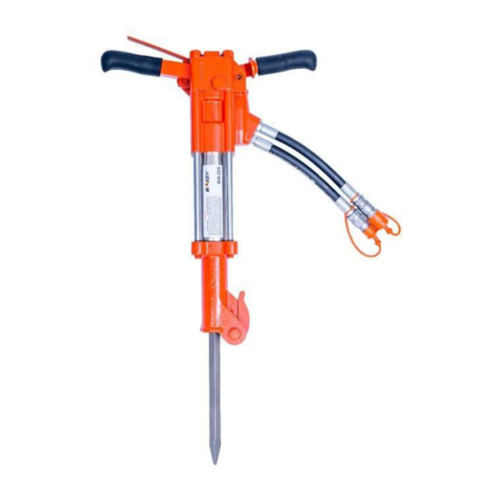
Summary of Contents for WIPIN BW20
- Page 1 BW20/BW20S HANDHELD HYDRAULIC BREAKERS USER MANUAL Safety, Operation and Maintenance...
-
Page 2: Table Of Contents
TABLE OF CONTENTS SAFETY GUIDELINE················································································ 2 i SAFETY PRECAUTIONS········································································2 ii SAFETY SYMBOLS·············································································· 3 iii LOCAL SAFETY REGULATIONS····························································3 TOOL STICKERS & TAGS....................4 HYDRAULIC HOSE REQUIREMENTS·························································5 HYDRAULIC EQUIPMENT·········································································6 OPERATION····························································································7 i PREPARATIONS BEFORE OPERATION··················································· 7 ii CHECK POWER SOURCE·····································································7 iii CHECK TOOL····················································································· 7 iv CHECK TIGGER·················································································... -
Page 3: Safety Guideline
SAFETY DANGER ! SERIOUS INJURY OR DEATH COUL RESULT FROM THE IMPROPER REPAI OR SERVICE OF THIS TOOL. Tool operators and maintenance personnel must always comply with the safety precautions given in this manual and on the stickers and tags attached to the equipment. -
Page 4: Safety Symbols
SAFETY SYMBOLS DANGER This is the safety alert symbol. It is used to alert you to potential personal injury hazards. Obey all safety messages that follow this symbol to avoid possible injury or death. WARNING This is the safety alert symbol. It is used to alert you to potential personal injury hazards. -
Page 5: Tool Stickers & Tags
TOOL STICKERS & TAGS • Safety labels and tags stick to all the equipment before they leave the factory • Do not exceed the rated limits of the equipment or use the equipment for applications beyond its design capacity • The information listed on the stickers shown, must be legible at all times. Replace decals if they become worn or damaged. -
Page 6: Hydraulic Hose Requirements
HYDRAULIC HOSE REQUIREMENTS TYPES OF HYDRAULIC HOSE There are three types of hydraulic hose that meet this requirement. They are: 1, Certified non-conductive 2, Wire-braided (conductive) 3, Fabric-braided (not certified or labeled non-conductive) Hose 1 can be used near electrical conductors Hose2,3 must never be used near electrical conductors. -
Page 7: Hydraulic Equipment
5. Back pressure value can not exceed 17bar. 6. Always replace hoses, couplings and other parts with replacement parts recommended by WIPIN Hydraulic Tools. 7. Supply hoses must have a minimum working pressure rating of 2500 psi/175 bar. 8. There must be a filter, it can filter the min size 25μm impurity. -
Page 8: Operation
OPERATION PRE-OPERATION PROCEDURES 1. Be sure the hydraulic breakers undamaged, no chips. CHECK POWER SOURCE 1. Using a calibrated flowmeter and pressure gauge, check that the hydraulic power source develops a flow of 15–22 lpm at 105–140 bar. 2. Make certain the hydraulic power source is equipped with a relief valve set to open at 155 bar maximum. -
Page 9: Charging The Accumulator
CHARGING THE ACCUMULATOR Charging Tools There are two parts 1, control assembly 2. ACCUMULATOR TESTER 3. Connection pic... - Page 10 Steps 1.connect Nitrogen tank and charging assembly tightly, check pic 1 2.connect accumulator tester on hydraulic tools. clockwise rotate the gauge, connect the chuck of the charging assembly to the charging valve on the accumulator tester once the gauge reaches maximum. Open the nitrogen tank, Adjust the snub valve to a charging pressure 5.Check the data of gauge, got the proper charge pressure.
-
Page 11: Troubleshooting
TROUBLESHOOTING PROBLEM CAUSE REMEDY Power unit not functioning Check power unit for power flow and pressure (15–24 lpm 105–140 bar) Couplers or hoses blocked Remove restriction Tool does not run Pressure and return line hoses Be sure hoses are reversed at ports connected to their proper ports Mechanical failure of piston or... -
Page 12: Specifications
SPECIFICATIONS Weight............................20kg Length............................60cm Width............................35cm Pressure range......................105-140bar Flow range......................7-9gpm/26-34lpm Normal flow.........................8gpm/30lpm Connect Size & Type..............3/8 in. Male Pipe Hose Ends System Type....................Open or Closed Center Port Size........................SAE 8 O-ring... -
Page 13: Accessories
BW18 T-HANDLE ILLUSTRATION... -
Page 14: Bw18 T-Handle Parts List
BW18 T-HANDLE ACCESSORIES ITEM NAME SPECIFICATION Tigger B 004B000001 AUTOMATIC VALVE BODY 9020003009 HEX NUT 9020003008 CHARGE VALVE 9010208003 HANDLE 004B000002 HANDLE GRIP 9010609007 Dust ring ROD WIPER 9020006002 O-RING 9020006003 BUSHING 004A000003 U-RING 9020006004 Circlip 9020009002 VALVE SPOOL 004B000003 COMPRESSION COIL SPRING 9020010001 HOSE WHIP... - Page 15 BREAKER FOOT ASSY 004A000019 O-RING 9020006006 ROD WIPER 9020006007 BACK UP WASHER 004A000020 U-RING 9020006008 SIDE ROD 004B000005 latch handle 004A000022 SPRING WASHER 9020004007 FOOT LATCH BOLT 9020001024 RUBBER SLEEVE 004A000023 Spring 9020010003 DETENT 9020013002...
- Page 16 Seal Ring ITEM NAME SPECIFICATION Dust ring ROD WIPER 9020006002 O-RING 9020006003 U-RING 9020006004 BACK-UP RING 9020006003 O-RING 9020006005 O-RING 9020006006 Dust ring ROD WIPER 9020006007 U-RING 9020006008 Pickaxe ITEM NAME SPECIFICATION Sharp Pickaxe 004A000041 Flat Pickaxe 004A000042...
-
Page 17: Bw18S Anti-Vib Illustration
BW18S ANTI-VIB ILLUSTRATION... -
Page 18: Bw18S Anti-Vib Parts List
ITEM NAME SPECIFICATION TOP PLATE 004A000001 LEVER 004A000002 ROLL PIN 9020013001 HANDLE Grip 9010609007 AUTOMATIC VALVE 9010208003 BODY CHARGE VALVE 9010405001 Dust ring ROD WIPER 9020006002 O-RING 9020006003 BUSHING ASSY 004A000003 U-RING 9020006004 Circlip 9020009002 VALVE SPOOL 004A000004 COMPRESSION COIL 9020010001 SPRING HOSE WHIP... - Page 19 PUSH PIN 004A000015 FLOW SLEEVE 004A000016 DETENT 004A000017 004C000035 HEX BUSHING -/” 004A000018 NYLOCK NUT 9020003009 BREAKER FOOT ASSY 004A000019 O-RING 9020006006 ROD WIPER 9020006007 004A000020 BACK UP WASHER U-RING 9020006008 SIDE ROD 004A000021 latch handle 004A000022 SPRING WASHER 9020004007 FOOT LATCH BOLT 9020001024 RUBBER SLEEVE...
- Page 20 Seal Ring ITEM NAME SPECIFICATION Dust ring ROD WIPER 9020006002 O-RING 9020006003 U-RING 9020006004 BACK-UP RING 9020006003 O-RING 9020006005 O-RING 9020006006 9020006007 Dust ring ROD WIPER U-RING 9020006008 Pickaxe ITEM NAME SPECIFICATION Sharp Pickaxe 004A000041 Flat Pickaxe 004A000042...
-
Page 21: Warranty
WARRANTY WIPIN Hydraulic Tools and their associated parts are warranted against defects in materials and workmanship for a period of twelve months from the date of purchase. And the authorized agents are entitled to confirm the material and manufacturing defects and repair. -
Page 22: Maintenance Records
MAINTENANCE RECORDS Product Recording Card Model: Product series: Date of purchasing: Seller’s company: Address: Post code: Telephone No: Fax: Note: Warranty Card Buyer’s company: Address: City: Post code: Telephone NO: Model: Product Series: Date of purchasing: Seller’s company: Address: City: Post code:...

Need help?
Do you have a question about the BW20 and is the answer not in the manual?
Questions and answers