
Summary of Contents for Kaukora FIL-SPL
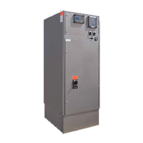
- Page 1 FIL-SPL Flow-through heater for central heating with 0 - 10 V EP 15-30 control unit USER MANUAL Kaukora LTD. D106159 r3.0...
-
Page 2: Table Of Contents
Transport ............................... 7 Physical installation ............................7 Supplied components ............................ 7 Structure and measures of FIL-SPL boilers ....................8 Models of 31 - 112 kW ..........................8 Models of 150 - 300 kW ..........................9 Models of 400 - 1600 kW ..........................10 Pipe connections ............................. - Page 3 Technical data ............................36 Technical specifications ..........................36 Electrical properties of FIL-SPL boilers ......................37 External control voltage (input) values and corresponding power steps in different modes....38 Status output voltage values and corresponding status data in different modes........39...
- Page 4 Recommended circulation pumps ....................... 41 Pressure drop table ............................. 42 Electrical circuit diagrams, models of 31 - 112 kW ..................43 Electrical circuit diagrams, models of 150 - 300 kW ................... 46 Electrical circuit diagrams, models of 400 - 1600 kW ................. 49...
-
Page 5: Important Information
FIL-SPL is CE marked and fulfills IP20. The CE marking means that Kaukora ensures that the product meets all regulations that are placed on it based on relevant EU directives. The CE mark is obligatory for most products sold in the EU, regardless where they are made. -
Page 6: Inspection Of The Installation
______________________________ Installer: ______________________________ Date: ______________________________ Signature: Electrical connections Main fuses (of the property) __________ A Fuses of FIL-SPL __________ A Primary side current transformers conversion ratio: __________ installed Secondary side current transformers installed Current transformer for observation of internal power... -
Page 7: Delivery And Handling
2. Delivery and handling Transport The FIL-SPL must be transported and stored vertically in a dry place. The FIL-SPL boiler should be lifted only from the lifting point on top of the boiler. Physical installation Mount FIL-SPL boiler on a firm base that can take the weight, preferably on a concrete floor or foundation. -
Page 8: Structure And Measures Of Fil-Spl Boilers
3. Structure and measures of FIL-SPL boilers Models of 31 - 112 kW Name Safety main switch (CB + switch disconnector + trip) Control unit Temperature gauge Control voltage switch Heating mode selection switch Temperature limiter Placeholder for sensor of dry-boiling preventer... -
Page 9: Models Of 150 - 300 Kw
Models of 150 - 300 kW Name Safety main switch (CB + switch disconnector + trip) Control unit Temperature gauge Control voltage switch Heating mode selection switch Temperature limiter Sensor of dry-boiling preventer Dry-boiling preventing unit Connection for draining Placeholder for electrical cables Lifting point... -
Page 10: Models Of 400 - 1600 Kw
Models of 400 - 1600 kW Name Temperature sensors (limiters and thermostat) Safety main switch (CB + switch disconnector + trip) Heating elements Power step contactors Connection for draining Power step fuses Temperature gauge Heating mode selection switch Thermostat/temperature limiter Control voltage switch Door for heating element service Dry-boiling preventing unit... -
Page 11: Pipe Connections
4. Pipe connections General pipe connections Pipe installation must be carried out in accordance with current norms and directives. Maximum of 10 bar safety valve must be installed in the supply pipe before any shut-off valve. The safety valve must be dimensioned so that its blowdown force with steam is equal to the boiler power. The size of the blowdown pipe cannot be reduced from its nominal size and must be positioned so that the steam discharge does not cause any personnel injuries or property damage. -
Page 12: System Diagram
Recommended external circulation pump can be found from Technical data, Recommended circulation pumps. Note! The water circulation in the FIL-SPL boiler must be ensured in all possible cases, unless the boiler is intentionally shut down with the main switch. The boiler can be used directly for heating or indirectly to produce hot water for general use. -
Page 13: Electrical Connections
Main switch The FIL-SPL boiler has integrated main switch. The main switch operates as an isolator switch if temperature limiter or dry-boiling preventer detects an error or in case of overload. -
Page 14: Connections
Mandatory external circulation pump The FIL-SPL boiler is a flow through heater, and thus requires an external circulation pump for circulating water in the boiler. While the boiler is enabled and there is possibility to shut off the heating medium circuit (with for example building automation), the water circulation in the boiler must be guaranteed in such cases with external circulation pump and piping (see System diagram as an example). -
Page 15: Optional Connections
Optional connections Outdoor temperature control The temperature of the boiler can be controlled automatically by measuring result of outdoor temperature sensor. The outdoor temperature sensor must be connected to X:14 and X:15. Use only Jäspi outdoor temperature sensor. Locate the temperature sensor in the shade on a wall facing north or north-west for preventing effect of for example morning sun. - Page 16 External on/off control The boiler can be remotely enabled or disabled with 230 VAC control voltage. This property can be used for example when the boiler is used as an additional immersion heater within heat pump system. Connect the external control voltage to X:4 (L) and X:5 (N). The heating is enabled while 230 VAC is connected to the X:4-5.
- Page 17 Load Monitor Load monitor is used for protecting main fuses of the property. The primary side current transformers must be located near main fuses of the property. Optimum place would be immediately after power meter. Note that primary side current transformers should have suitable conversion ratio. The load monitor uses measured values of Jäspi current transformers (secondary side current transformers) and limits the power of the boiler while one of the phases has overcurrent.
- Page 18 More information can be found from Menu 2.3 Effect factor. 0 - 10 V status output Status data of the FIL-SPL boiler can be shown out via analog voltage message. Connect status output to X:6 (+) and X:7 (-). As a status, following information can be given: ...
- Page 19 Alarm relay output of the main switch The FIL-SPL boiler has an extra alarm relay in the main switch. If the main switch trips for some reason, the changeover contact in the main switch can be used as an alarm source for example for building automation.
- Page 20 Status output of control unit The FIL-SPL boiler can indicate the On/Off status of the control unit. The information can be used for example in building automation. Connect the status information of the control unit to X:27 and X:28 (NC).
-
Page 21: Commissioning And Adjusting
4. Turn the main switch first to “0” (off) position (especially if the main switch has tripped) 5. Start the FIL-SPL boiler by turning the main switch to “I” (on) position 6. Turn the control switch to position “I” (on) 7. -
Page 22: Control
7. Control Display unit A. Display Instructions, settings and operational information are shown on the display. B. Back button The back button is used to: Move back in menu (save modifications) Move to menu from default screen C. Move up button The move up button is used to: ... -
Page 23: Menu System
Menu system The menu system consists of four main menus; info, service, tests and Setup. Menu 1 - Info Display of temperature and other operating information and access to the service menu Menu 2 - Service Advanced settings and access to the test and setup menus. Menu 3 - Test Manually Advanced tests for maintain and service. -
Page 24: Control - Menus
8. Control - Menus Menu 1 - Info Overview Menu 1 - Info Temp (informative) Setting (default) OutdoorComp ( while enabled Step (informative) Maxtemp AC in (informative) Mintemp Menu 2 - Curve Service Parallel Menu 1.1 Temp Currently measured boiler temperature. Informative reading. Menu 1.1.1/1 Setting Target temperature of the boiler. -
Page 25: Menu 1.1.1/2 Outdoorcomp
Menu 1.1.1/2 OutdoorComp Settings for outdoor temperature control. This menu is shown when the outdoor temperature control is enabled. The menu consists of four submenus. Maxtemp is the maximum allowable boiler temperature ie. cuts the curve at high end (programmable temperature limiter). -
Page 26: Menu 1.2 Step
Parallel is parallel adjusting of the heating curve of the boiler. The value is simply added to or subtracted from the curve values. With this way, user can achieve fine adjusting for heating curve. See figure “example parallel” below. Setting range (-20) - 20 °C ... -
Page 27: Menu 2 - Service
Menu 2 - Service Overview Menu 2 - Service Step (informative) Time Current (informative) Marginal Effect factor S.time test Menu 3 - Test manually Menu 4 - Setup Menu 2.1 Step Currently used power step. Informative reading. Menu 2.1.1 Max Maximum number of allowable power steps. -
Page 28: Menu 2.2.1 Max
Note! The setting values are indicative as many issues affects to the accuracy, such as accuracy of used current transformers. The value to be used is dependent on lowest power step of used FIL-SPL, phase-to-neutral voltage and conversion ratio of primary side current transformers. Calculation: ������������... -
Page 29: Menu 2.3 Effect Factor
Menu 2.3 Effect factor The effect factor is used by observation of internal power consumption for an alarm. The control unit observes power consumption when increasing power steps. If multiple power step increases are done without affecting measured power, the control unit will give notice “Error in power measurement” on the display and activate the alarm relay. -
Page 30: Menu 3 - Test Manually
Menu 3 - Test manually Overview Menu 3 - Test manually Contactor 1 Contactor 2 Contactor 3 Contactor 4 Alarm 0 - 10 V Menu 3.1 Contactor 1 Force control of contactor 1. Enable contactor 1 by setting value to ”1” and disable by setting value to ”0”. Settable value: ... -
Page 31: Menu 4 - Setup
Menu 4 - Setup Overview Menu 4 - Setup Language Model Input Output OutdoorComp Menu 4.1 Language (selected language) The actual reading of Menu 4.1 is currently selected language. The language of the control unit can be selected here. Settable value: ... -
Page 32: Menu 4.4 Output
Menu 4.4 Output Setting of 0 - 10 V status voltage output. More information about voltage levels and status data content can be found from Technical data, Status output voltage values and corresponding status data in different modes. Settable value: ... -
Page 33: Service
Note! When replacing components on FIL-SPL only replacement parts from Kaukora may be used. As the boiler operation is fully automatic, servicing and operating is very easy. However, each user must thoroughly familiarize themselves with the boiler controls, such as: boiler temperature control, temperature limiter, thermostats and control switches. -
Page 34: Disturbances In Comfort
Disturbances in comfort Troubleshooting Note! The FIL-SPL boiler might have an external control voltage that the main switch does not turn off. Basic actions Note! After power cut there is two hours time delay before full power is taken into use. -
Page 35: Accessories
Accessories Jäspi current transformers (200 018) Jäspi current transformers are for load monitoring of main fuses. The same type of current transformers can be used also for observation of internal power consumption. Jäspi outdoor temperature sensor (200 035) Jäspi outdoor temperature sensor is to be used when the outdoor temperature control is enabled. -
Page 36: Technical Data
400 V 3 AC 50 Hz Voltage of control unit (internally connected) 230 V 1 N AC 50 Hz ± 10 % Power See Electrical properties of FIL-SPL boilers Maximum current See Electrical properties of FIL-SPL boilers Recommended fuse See Electrical properties of FIL-SPL boilers... -
Page 37: Electrical Properties Of Fil-Spl Boilers
Electrical properties of FIL-SPL boilers In the table below is presented model, power, nominal current consumption, recommended fuse, and informative cabling. Note that the size and type of the supply cable is always determined on a project-specific basis according to the cable lengths, installation method and applicable standards. -
Page 38: External Control Voltage (Input) Values And Corresponding Power Steps In Different Modes
External control voltage (input) values and corresponding power steps in different modes. The function must be selected from the setup menu. Note that the max. setting values are overruling, i.e. if maximum number of power steps has been limited to 5, the control unit will not enable power steps above 5 even though the external control voltage indicates higher power. Power Power Power Inv. -
Page 39: Status Output Voltage Values And Corresponding Status Data In Different Modes
Status output voltage values and corresponding status data in different modes. The function must be selected in the setup menu. Power Power Temp. T.calc Model 15 Model 7 (temp.) [Pwr [Pwr step] step] [°C] [°C] 0,00 0,00 4,00 20,00 4,00 20,00 0,70 1,40... -
Page 40: Temperature Sensor Resistance Values In Different Temperatures
Temperature sensor resistance values in different temperatures The temperature sensors are negative temperature coefficient resistor. In the table below is presented resistor values of the sensors at different temperatures. Boiler temperature (NTC22K) Outdoor temperature sensor (151R) Temperature Resistance Temperature Resistance [°C] [kΩ] [°C]... -
Page 41: Recommended Circulation Pumps
Recommended circulation pumps The water circulation inside the boiler must be ensured with an external pump. Recommended pump types versus different FIL-SPL models. Model Pump FIL-SPL 31.5 - 300 kW UPS 25 - 80 F FIL-SPL 400 kW UPS 32 - 50 F... -
Page 42: Pressure Drop Table
Pressure drop table The table below presents the pressure drop with different FIL-SPL models. Model Min. flow [l/s] Nom. flow [l/s] Flow speed [m/s] Pressure drop [Pa] Pressure drop @ Temp. Rise 20 °C [mm H2O] FIL-SPL 31.5 FIL-SPL 42... -
Page 43: Electrical Circuit Diagrams, Models Of 31 - 112 Kw
Electrical circuit diagrams, models of 31 - 112 kW... -
Page 46: Electrical Circuit Diagrams, Models Of 150 - 300 Kw
Electrical circuit diagrams, models of 150 - 300 kW... -
Page 49: Electrical Circuit Diagrams, Models Of 400 - 1600 Kw
Electrical circuit diagrams, models of 400 - 1600 kW... - Page 53 We reserve rights to changes. © Kaukora Ltd 2019 D106159 r4.0...