Advertisement
Quick Links
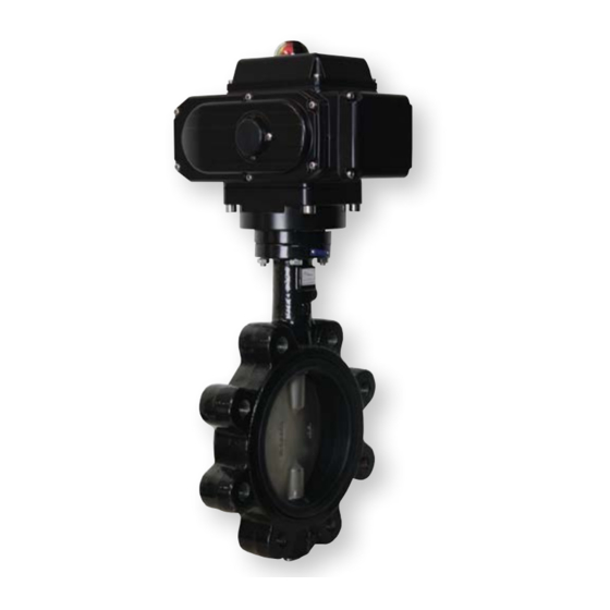
Series WE20 Butterfly Valve
Specifications - Installation and Operating Instructions
WE20-CHD00-LE
The Series WE20 Butterfly Valve is offered in lug or wafer body styles and is equipped
with a PTFE or EPDM liner. The most critical aspect of the Series WE20 Butterfly
Valves is the cartridge seat design, which alleviates installation problems associated
with common "dove tail design" seats. Valve torques are lower and more consistent
as the seat dynamics are not dependent on being coupled between two flanges.
Precision machining of the disc and body allow the cartridge design to maintain a
tighter disc to seat tolerance, providing a perfect low torque seal each and every time
the valve is cycled. The seat to disc seal is independent of flange support and capable
of full rated dead end service.
Actuators are directly mounted creating a compact assembly for tight spaces. Limit
switches are able to be mounted directly to the valves allowing for remote position
indication.
The Series WE20 can be configured with either an electric or pneumatic actuator.
Electric actuators are available in weatherproof or explosion-proof, a variety of supply
voltages and two-position or modulating control. Two-position actuators use the supply
voltage to drive the valve open or closed, while the modulating actuator accepts a
4-20 mA input for valve positioning. Actuators feature thermal overload protection and
permanently lubricated gear train. The pneumatic double acting actuator uses an air
supply to drive the valve open and closed. The actuator has two supply ports, with one
driving the valve open and the other driving the valve closed. Spring return pneumatic
actuators use the air supply to open the valve, and internally loaded springs return the
valve to the closed position.
The pneumatic double acting actuator uses an air supply to drive the valve open
and closed. The actuator has two supply ports with one driving the valve open and
the other driving the valve closed. Spring return pneumatic actuators use the air
supply to open the valve and internally loaded springs return the valve to the closed
position. Also available is the SV3 solenoid valve to electrically switch the air supply
pressure between the air supply ports for opening and closing the valve. Actuators
are constructed of anodized and epoxy coated aluminum for years of corrosion free
service.
DWYER INSTRUMENTS, INC.
P.O. BOX 373 • MICHIGAN CITY, INDIANA 46360, U.S.A.
WE20-ETD04-LE-A
WE20-EDA06-LE
WE20-CDA04-WP-AA07
SPECIFICATIONS
VALVE
Service: Compatible liquids, gases, and
steam.
Body: 2-way, wafer or lug butterfly.
Line Sizes: 2 to 12˝.
End Connections: Lug and water
pattern designed for flanges that are
ANSI Class 125 (B16.1) and ANSI Class
150 (B16.5) dimension.
Pressure Limits: 225 psi (15.5 bar).
Wetted Materials: Body Material: Ductile
iron; Disc: 316 SS; Seat: EPDM or
PTFE; O-ring: EPDM; Stem: 410 SS.
Temperature Limits: Disc: EPDM:
-50 to 250°F (-46 to 121°C); PTFE: 0 to
300°F (-18 to 149°C).
Bearings: Nylatron.
Operator: 2 to 6˝ 10-position locking
hand lever; 8 to 12˝: manual gear.
ACTUATORS
Pneumatic "DA" and "SR" Series
Type: DA series is double acting and
SR series is spring return (rack and
pinion).
Normal Supply Pressure: DA: 40 to
115 psi (2.7 to 7.9 bar); SR: 70 to 115 psi
(4.8 to 7.9 bar).
Maximum Supply Pressure: 120 psi
(8.6 bar).
Air Connections: DA03 to DA11: 1/4˝
FNPT; SR03 to SR11: 1/4˝ FNPT.
Housing Material: Anodized aluminum
body and epoxy coated aluminum end
caps.
Temperature Limits: -40 to 176°F (-40
to 80°C).
Accessory Mounting: NAMUR
standard.
Phone: 219-879-8000
Fax: 219-872-9057
Bulletin V-WE20
WE20-CDA04-WP-NN08
Electric "TD" and "MD" Series
Power Requirements: 110 VAC, 220
VAC or 24 VAC.
Power Consumption: See page 9.
Cycle Time (per 90°): TD01 and MD01:
4 s; TD02 and MD02: 20 s; TD03 and
MD03: 30 s; TD04 and MD04: 30 s;
TD05 and MD05: 30 s; TD06 and
MD06: 45 s; TD07 and MD07: 30 s.
Duty Rating: 85%.
Enclosure Rating: NEMA 4X (IP67).
Housing Material: Powder coated
aluminum.
Temperature Limits: -22 to 140°F (-30
to 60°C).
Electrical Connection: 1/2˝ female NPT.
Modulating Input: 4-20 mA.
Standard Features: Manual override,
position indicator, and TD models come
with two limit switches.
Electric "TH" and "MH" Series
Power Requirements: 110 VAC, 220
VAC, 24 VAC or 24 VDC.
Power Consumption: See page 9.
Cycle Time (per 90°): See page 9.
Duty Rating: See page 9.
Enclosure Rating: NEMA 7, designed
to meet hazardous locations: Class I,
Group C & D; Class II, Group E, F & G;
Division I & II.
Housing Material: Powder coated
aluminum.
Temperature Limits: -22 to 140°F (-30
to 60°C).
Electrical Connection: 1/2˝ female NPT.
Modulating Input: 4-20 mA.
Standard Features: Position indicator
and two limit switches.
www.dwyer-inst.com
e-mail: info@dwyermail.com
Advertisement

Summary of Contents for W.E. Anderson WE20 Series
- Page 1 Bulletin V-WE20 Series WE20 Butterfly Valve Specifications - Installation and Operating Instructions WE20-CHD00-LE WE20-CDA04-WP-NN08 WE20-ETD04-LE-A WE20-EDA06-LE WE20-CDA04-WP-AA07 The Series WE20 Butterfly Valve is offered in lug or wafer body styles and is equipped SPECIFICATIONS with a PTFE or EPDM liner. The most critical aspect of the Series WE20 Butterfly VALVE Electric “TD”...
- Page 2 MODEL CHART Popular Popular Popular NEMA 4X Popular NEMA 4X Popular Double Acting Spring Return Two Position Modulating Hand Operated Pneumatic Pneumatic Electric Electric Size (gal/min) Model Model Model (110 VAC) Model (110 VAC) Model 2˝ WE20-AHD00-WE WE20-ADA03-WE WE20-ASR04-WE WE20-ATD02-WE-A WE20-AMD02-WE-A 2-1/2˝...
- Page 3 AUTOMATED VALVE DRAWINGS DOUBLE ACTING PNEUMATIC ACTUATOR NPT 2˝ 2-1/2˝ 3˝ 4˝ 5˝ 6˝ 8˝ 10˝ 12˝ 10-5/8˝ 11-1/8˝ 12-1/4˝ 12-15/16˝ 13-7/8˝ 14-15/16˝ 17-1/8˝ 19-1/16˝ 21-13/16˝ [269.13] [283.02] [310.37] [328.03] [353.12] [379.22] [435.31] [483.6] [554.34] 3-1/4˝ 3-1/4˝ 3-11/16˝ 4˝ 4-1/4˝ 4-13/16˝...
-
Page 4: Pneumatic Actuator
PNEUMATIC ACTUATOR Failures Inspection Items Corrective Action Note: For optimal operation, pneumatic actuators should be run with a supply of Pneumatic 1. Check the solenoid valve. Is the 1. Replace the solenoid clean, lubricated air. actuator coil burnt out or is the solenoid valve coil or remove debris. - Page 5 Pneumatic Actuators Bill of Materials Part Number Quantity Part Name Material Cylinder Extruded Aluminum Alloy Output Shaft Stainless Steel O-ring Fluorine Silicon Rubber Bearing Nylon46 Adjusting Cam Stainless Steel Thrust Bearing Nylon46 Bearing Nylon46 O-ring Fluorine Silicon Rubber Bearing Nylon46 Gasket Stainless Steel Damping Ring...
- Page 6 MODEL CHART - DOUBLE ACTING ACTUATOR TORQUE Double Acting Pneumatic Actuator Output Torque (in-lb) Air Pressure Model 40 psi 50 psi 60 psi 70 psi 80 psi 90 psi 100 psi 110 psi 115 psi ACT-DA01 ACT-DA02 ACT-DA03 ACT-DA04 ACT-DA05 1089 1148 ACT-DA06...
-
Page 7: Field Wiring
Electric Actuators Wiring Diagram: ACT-TH & ACT-MH Wiring Diagrams for TH03-A to TH11-A: 110 VAC, TH03-B to TH11-B: 220 VAC, TH03-C to TH11-C: 24 VAC OPTIONAL OPTIONAL PSC MOTOR PSC MOTOR BRAKE BRAKE SW. #2 OPEN LIMIT SW. #2 OPEN LIMIT OPTIONAL HEATER OPTIONAL HEATER SW. - Page 8 Wiring Diagrams for MH03-A to MH11-A: 110 VAC, MH03-B to MH11-B: 220 VAC, MH03-C to MH11-C: 24 VAC GREEN GREEN CAPACITOR JUMPER SET FOR JUMPER SET FOR PSC MOTOR FAIL CLOSE UPON FAIL OPEN UPON LOSS OF CONTROL LOSS OF CONTROL SW.
- Page 9 Electric Actuators Wiring Diagram: ACT-TD & ACT-MD Note: To speed up installation of the control wires to the ACT-MDXX modulating actuator, it is recommended to remove the control module from the actuator. The control module can be removed by removing the two mounting screws on the left Wiring Diagrams for and right of the control module.
- Page 10 Electric Actuators Performance Rating TD02 and MD02 (MD Not Available in 24 VDC) TH04 and MH04 Voltage 110 VAC 220 VAC 24 VAC 24 VDC Voltage 110 VAC 220 VAC 24 VAC 24 VDC Cycle Time 20 s 20 s 20 s 20 s Cycle Time (Two-Position)
-
Page 11: Maintenance/Repair
MAINTENANCE/REPAIR Upon final installation of the Series WE, only routine maintenance is required. The Series WE is not field serviceable and should be returned if repair is needed. Field repair should not be attempted and may void warranty. WARRANTY/RETURN Refer to “Terms and Conditions of Sale” in our catalog and on our website. Contact customer service to receive a Return Goods Authorization number before shipping the product back for repair. - Page 12 NOTES __________________________________________________________________________________________________________________________________________ __________________________________________________________________________________________________________________________________________ __________________________________________________________________________________________________________________________________________ __________________________________________________________________________________________________________________________________________ __________________________________________________________________________________________________________________________________________ __________________________________________________________________________________________________________________________________________ __________________________________________________________________________________________________________________________________________ __________________________________________________________________________________________________________________________________________ __________________________________________________________________________________________________________________________________________ __________________________________________________________________________________________________________________________________________ __________________________________________________________________________________________________________________________________________ __________________________________________________________________________________________________________________________________________ __________________________________________________________________________________________________________________________________________ __________________________________________________________________________________________________________________________________________ __________________________________________________________________________________________________________________________________________ __________________________________________________________________________________________________________________________________________ __________________________________________________________________________________________________________________________________________ __________________________________________________________________________________________________________________________________________ __________________________________________________________________________________________________________________________________________ __________________________________________________________________________________________________________________________________________ __________________________________________________________________________________________________________________________________________ __________________________________________________________________________________________________________________________________________ __________________________________________________________________________________________________________________________________________ __________________________________________________________________________________________________________________________________________ __________________________________________________________________________________________________________________________________________ __________________________________________________________________________________________________________________________________________ ©Copyright 2022 Dwyer Instruments, Inc. Printed in U.S.A. 7/22 FR# 444279-00 Rev. 6 DWYER INSTRUMENTS, INC.
Need help?
Do you have a question about the WE20 Series and is the answer not in the manual?
Questions and answers