Table of Contents
Advertisement
Quick Links
Advertisement
Table of Contents

Summary of Contents for ATO AM2011
- Page 1 Humidity Sensor, Capacitive AM2011 User Manual...
-
Page 2: Product Overview
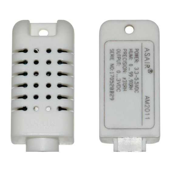
User Manual AM2011 1. Product Overview AM2011 is a humidity sensitive capacitive temperature and humidity sensor, and the sensor signal adopts the analog voltage output method. This module has high precision, high reliability, good consistency, and with temperature compensation, to ensure good long-term stability, easy to use and low price, especially suitable for enterprises with strict quality and cost requirements. -
Page 3: Interface Definition
User Manual AM2011 5.Interface Definition 5.1 Pin Assignment Table 1:Pin Assignment Color Name Description Power Supply(3.3V-5.5V DC) Yellow Humidity Output(0-3V DC) Hout Black Ground Wire Temperature is NTC10K White Tout thermistor Figure 1: Pinout Diagram 5.2 Power Pin (VDD GND)... -
Page 4: Sensor Performance
User Manual AM2011 6. Sensor performance 6.1 Relative humidity Table 2: Relative Humidity Performance Table Parameter Condition Unit Measuring range 99.9 [1] This accuracy is the accuracy index tested at ±3 25℃ Precision 25°C and 5V when the sensor is tested at the Repeatability factory. -
Page 5: Electrical Characteristics
Temperature output NTC 10K 7.1 Standard humidity output voltage (without debugging) (condition: at 25℃, Vin=5.0V) Unit: V Table 6: AM2011 Standard Humidity Output Voltage Correspondence Table Relative humidity(%RH) Output voltage (V) Full-scale temperature compensation, full-scale microcontroller calibration output, output impedance: below 5kΩ. -
Page 6: Standard Testing Conditions
User Manual AM2011 7.6 NTC10K Thermistor Temperature Corresponding Resistance Table Standard temperature output resistance (no debugging) Table 8: 10K NTC B.3435 temperature and resistance corresponding table Temperature(℃) Resistance(kΩ) 27.90 18.22 12.12 8.31 5.80 4.12 3.00 2.21 1.66 Note: 10kΩ NTC See attached table for details: Resistance-Temperature Characteristics Table 8. - Page 7 User Manual AM2011 Attached table NTC 10K resistance-temperature characteristic table T(℃) RMin(KΩ) RNor(KΩ) RMax(KΩ) T(℃) RMin(KΩ) RNor(KΩ) RMax(KΩ) 218.9971 228.2376 237.8441 28.9630 29.5745 30.1959 206.2948 214.8696 223.7783 27.6951 28.2671 28.8480 194.4226 202.3826 210.6475 26.4908 27.0257 27.5687 183.3204 190.7126 198.3831 25.3463 25.8466...
- Page 8 User Manual AM2011 T(℃) RMin(KΩ) RNor(KΩ) RMax(KΩ) T(℃) RMin(KΩ) RNor(KΩ) RMax(KΩ) 6.0986 6.1899 6.2818 1.5032 1.5469 1.5918 5.8845 5.9746 6.0655 1.4613 1.5043 1.5484 5.6790 5.7680 5.8578 1.4208 1.4630 1.5063 5.4818 5.5697 5.6584 1.3816 1.4231 1.4656 5.2926 5.3793 5.4669 1.3437 1.3844 1.4262...
-
Page 9: Application Information
The quality of the signal wire will affect the quality of the voltage output. It is recommended to use a high-quality shielded wire. 10.7 Welding information For manual soldering, the contact time must be less than 3 seconds at temperatures up to 300°C. 10.8 Product upgrade - 8 - For details, please consult the ATO Electronic Technology Department. -
Page 10: License Agreement
3. The product should be within the shelf life. ATO is only responsible for products that are defective when used in accordance with the technical conditions of the product. ATO makes no warranties, guarantees or written representations about the use of its products in those particular applications.
Need help?
Do you have a question about the AM2011 and is the answer not in the manual?
Questions and answers