Table of Contents
Advertisement
Quick Links
maxAI 430i & maxAI 430iv
Technical Manual
© August 2021 by maximatecc. All Rights Reserved.
The contents of this manual are intended for the sole benefit of maximatecc's customer and must not be disclosed
to persons outside of the intended user's company without maximatecc's permission. This material is regarded
as intellectual property and the user is, therefore advised that he/she must treat its contents as being confidential
between maximatecc and the User Company.
Rev C 6/17/2020
Advertisement
Table of Contents

Related Manuals for maximatecc maxAI 430i


Summary of Contents for maximatecc maxAI 430i
- Page 1 © August 2021 by maximatecc. All Rights Reserved. The contents of this manual are intended for the sole benefit of maximatecc’s customer and must not be disclosed to persons outside of the intended user’s company without maximatecc’s permission. This material is regarded as intellectual property and the user is, therefore advised that he/she must treat its contents as being confidential between maximatecc and the User Company.
-
Page 2: Table Of Contents
1. Scope and Use of This Manual ..........1 2. Installation Instructions ............2 2.1 maxAI 430i & maxAI 430iv Flush Mounting ........2 2.2 maxAI 430i & maxAI 430iv Hole Mounting ........3 2.3 maxAI 430i & maxAI 430iv Ram Mounting ........4 3. - Page 3 5. Appendices ................ 53 5.1 Appendix A: Transmission Parameters ......... 53 5.2 Appendix B: Fault Codes ............... 54 5.3 Appendix C: Analog Inputs ............55 5.4 Appendix D: Gauge abbreviations ..........56 6. Troubleshooting Guide ............57 7. Revision History ..............59 Rev C 6/17/2020...
-
Page 4: Scope And Use Of This Manual
m a x A I 4 3 0 i v T E C H N I C A L M A N U A L 1. Scope and Use of This Manual …provide the reader with enough background information to understand the overall operation of the maxAI 430iv… The intent of this manual is to provide the reader with all of the information required to install and troubleshoot the maxAI 430iv display, as well as to provide background information regarding the overall operation of a data-bus. -
Page 5: Installation Instructions
T E C H N I C A L M A N U A L 2. Installation Instructions 2.1 maxAI 430i & maxAI 430iv Flush Mounting Recommended panel cut-out size for flush mounting is 146.5mm (5.77”) x 110.9mm (4.37”) with 6.6mm (0.26”) radius on the corners. -
Page 6: Maxai 430I & Maxai 430Iv Hole Mounting
T E C H N I C A L M A N U A L 2.2 maxAI 430i & maxAI 430iv Hole Mounting Recommended panel cut-out size for 3” hole mounting is 85.8mm (3.38”.) Insert the instrument in the panel and secure the brackets over the mounting points using supplied washer and screw. -
Page 7: Maxai 430I & Maxai 430Iv Ram Mounting
T E C H N I C A L M A N U A L 2.3 maxAI 430i & maxAI 430iv Ram Mounting No panel cut-out is necessary for Ram mounting. Determine mounting location for Ram mount and secure the round ball base. - Page 8 4 3 0 i v T E C H N I C A L M A N U A L 2.4 maxAI 430i & maxAI 430iv Wiring Both connectors are used to make the electrical connections. Only available for maxAI430iv model Co n nec tor J 1 ...
-
Page 9: Display Features
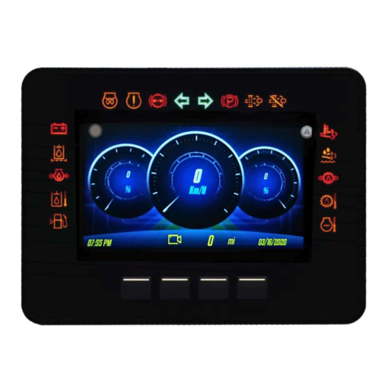
(LOW/HIGH). One input (6) is dedicated to read current, ideal for 4-20mA sensors. See Appendix C section for additional information. 3. Display Features The image below is a detail of the maxAI 430i & maxAI 430iv display features. LCD Warning Light Indicator Popup Indicator... -
Page 10: Navigation & Keypad Functions
m a x A I 4 3 0 i v T E C H N I C A L M A N U A L 3.1 Navigation & Keypad Functions Basic Navigation When the 3rd button is pressed, the main menu items are displayed. Rev C 6/17/2020... - Page 11 m a x A I 4 3 0 i v T E C H N I C A L M A N U A L Pressing the Arrow Keys will move the menu selector to the other menu items. Pressing the Select Key on the highlighted menu item will open up the particular menu page.
- Page 12 m a x A I 4 3 0 i v T E C H N I C A L M A N U A L Pressing the Arrow Keys will move the selection bar to other menu items. When the desired item is highlighted by the selection bar, pressing Select Key will select that item.
-
Page 13: Settings And Menu Options
m a x A I 4 3 0 i v T E C H N I C A L M A N U A L Pressing the Cancel Key will return to the previous menu page. 3.2 Settings and Menu Options Getting Started Basic display settings such as date/time, backlighting, color mode and contrast are adjusted on the maxAI 430iv display. -
Page 14: Accessing The Video Input
m a x A I 4 3 0 i v T E C H N I C A L M A N U A L 3.3 Accessing the Video Input The camera video can be configured to be activated by the Keypad 2 button or by a CAN message from channel 0 or channel 1 from the PC Configuration Tool. -
Page 15: Display Menu Navigation
m a x A I 4 3 0 i v T E C H N I C A L M A N U A L 3.5 Display Menu Navigation The display menu is broken down into 4 items with sub menus under each item as follows: 1. -
Page 16: Settings
m a x A I 4 3 0 i v T E C H N I C A L M A N U A L 3.5.1 Settings Select settings from main menu by scrolling to Settings and pressing the Select Key 3.5.1.1 Date/Time Setting Date/Time Change the values using the Arrow Keys... -
Page 17: Illumination
m a x A I 4 3 0 i v T E C H N I C A L M A N U A L 3.5.1.2 Illumination Changing Color Theme Select Color Theme. Select theme by scrolling to desired theme using the Arrow Keys Once the desired color theme is highlighted, press the Select Key to set the color theme. - Page 18 m a x A I 4 3 0 i v T E C H N I C A L M A N U A L Changing Display Brightness Select Set Brightness. Adjust the contrast by scrolling up or down using the Arrow Keys Once the desired contrast has been reached, set the contrast by pressing the Select Key .
- Page 19 m a x A I 4 3 0 i v T E C H N I C A L M A N U A L Changing Keypad Backlighting Select Keypad Backlight. Select ON or OFF by using the Arrow Keys .
-
Page 20: Language/Units
m a x A I 4 3 0 i v T E C H N I C A L M A N U A L 3.5.1.3 Language/Units Selecting Language Select Language. Select language by scrolling to desired language using the Arrow Keys Once the desired language is highlighted, press the Select Key to set the language. - Page 21 m a x A I 4 3 0 i v T E C H N I C A L M A N U A L Selecting Units Select Units. Select units by scrolling to desired unit of measure using the Arrow Keys Once the desired unit of measure is highlighted, press the Select Key to set the units.
-
Page 22: Trip Information
m a x A I 4 3 0 i v T E C H N I C A L M A N U A L 3.5.1.4 Trip Information Resetting Trip Hourmeter Select Reset Trip Hourmeter. Press the Select Key to confirm reset or Cancel Key to cancel. - Page 23 m a x A I 4 3 0 i v T E C H N I C A L M A N U A L Select Reset Trip Odometer. Press the Select Key to confirm reset or Cancel Key to cancel. At this point the screen will return to the Trip Information sub menu.
-
Page 24: Communications
m a x A I 4 3 0 i v T E C H N I C A L M A N U A L 3.5.1.5 Communications Communications settings is protected with pin, enter pin and proceed, please refer to Change Pin Code section for futher information about Pin. -
Page 25: Service Interval
m a x A I 4 3 0 i v T E C H N I C A L M A N U A L Select baud rate by scrolling to desired rate using the Arrow Keys Once the desired baud rate is highlighted, press the Select Key to set the rate. - Page 26 m a x A I 4 3 0 i v T E C H N I C A L M A N U A L Select Enable or Disable by using the Arrow Keys Once the desired option is highlighted, press the Select Key to make your selection.
- Page 27 m a x A I 4 3 0 i v T E C H N I C A L M A N U A L Select Service Interval Mode Select Odometer or Hourmeter by using the Arrow Keys Once the desire option is highlighted, press the Select Key to make your selection.
- Page 28 m a x A I 4 3 0 i v T E C H N I C A L M A N U A L The digit being adjusted will be highlighted. Adjust the digit by using the Arrow Keys Once the desired value is reached select it and move to the next digit by pressing the Select Key .
-
Page 29: Change Pin Code
m a x A I 4 3 0 i v T E C H N I C A L M A N U A L A confirmation window will appear. Press the Select Key to confirm the reset. If you do not wish to reset, press the Cancel Key to return to the service interval sub menu. - Page 30 m a x A I 4 3 0 i v T E C H N I C A L M A N U A L Current Pin Code The digit being entered will be highlighted. Select the digit by using the Arrow Keys Once the desired value is reached select it and move to the next digit by pressing the Select Key .
-
Page 31: Instrument Setup
m a x A I 4 3 0 i v T E C H N I C A L M A N U A L 3.5.2 Instrument Setup Select instrument setup from main menu by scrolling to Instrument Setup and pressing the Select Key 3.5.2.1 Demo Turning Demo Mode On/Off Select Demo. -
Page 32: Built-In Configuration
m a x A I 4 3 0 i v T E C H N I C A L M A N U A L 3.5.2.2 Built-In Configuration Selecting Built-In Configuration Communications settings is protected with pin, enter pin and proceed, please refer to Change Pin Code section for futher information about Pin. - Page 33 m a x A I 4 3 0 i v T E C H N I C A L M A N U A L Select Built-In Configuration You will have the option to configure the instrument Screens or the instrument Output type. Select Output or Screens by scrolling to desired option using the Arrow Keys Once the desired option is highlighted, press the Select Key Setting up Screens...
- Page 34 m a x A I 4 3 0 i v T E C H N I C A L M A N U A L Use the Arrow Keys to scroll through the five available screens. To turn the screen ON/OFF press the Select Key while on the highlighted screen.
- Page 35 m a x A I 4 3 0 i v T E C H N I C A L M A N U A L The instrument to be configured will be highlighted. To adjust the highlighted instrument press the Select Key or use the Arrow Keys to scroll to a diferent instrument.
- Page 36 m a x A I 4 3 0 i v T E C H N I C A L M A N U A L When selecting an analog signal source, the analog input and type must be selected. After selecting Analog, the input screen will appear.
- Page 37 m a x A I 4 3 0 i v T E C H N I C A L M A N U A L Once the type is selected, the screen will highlight the settings for the input and type. These settings cannot be changed in Built-In Configuration.
- Page 38 m a x A I 4 3 0 i v T E C H N I C A L M A N U A L Before finalizing changes and returning to the Built-In Configuration sub menu, you will be prompted to confirm saving changes.
- Page 39 m a x A I 4 3 0 i v T E C H N I C A L M A N U A L Select Output Use the Arrow Keys to scroll through the Output Types. To select the output, press the Select while on the highlighted output type.
-
Page 40: Dpf Regeneration
m a x A I 4 3 0 i v T E C H N I C A L M A N U A L 3.5.2.3 DPF Regeneration Selecting DPF Regeneration Select DPF Regeneration DPF Regeneration information will be displayed. The default state when entering DPF Regeneration screen will be Regen Mode Auto, the banner in the top of the screen in indicate the current state. - Page 41 m a x A I 4 3 0 i v T E C H N I C A L M A N U A L Inhibit Regen Key. Inhibit Regen OFF Inhibit Regen ON The Inhibit Regen Key will work as a toggle switch that will allow the operator to postpone the regen cycle.
- Page 42 m a x A I 4 3 0 i v T E C H N I C A L M A N U A L Force Regen Key. Force Regen OFF Force Regen ON Once the Regen Mode Manual is active then the Force Regen key will be available. The Force Regen Key will work as a push button that will allow the operator to perform the regen cycle.
- Page 43 m a x A I 4 3 0 i v T E C H N I C A L M A N U A L Exhaust System Cleaning Lamps. This feature is only available for models maxAI430i and maxAI430iv. Lamp 14 Lamp 13 Lamp 13 –...
-
Page 44: Fault Codes
m a x A I 4 3 0 i v T E C H N I C A L M A N U A L Lamp 14 - Exhaust System Cleaning Inhibited Lamp Lamp 14 will turn on when the cluster receives SPN 3703 as inhibited due to due to the Diesel Particulate Filter Regeneration Inhibit Switch. -
Page 45: Inactive Fault Codes
m a x A I 4 3 0 i v T E C H N I C A L M A N U A L Active fault codes will be displayed. Use the Arrow Keys to select Engine, Transmission, or Retarder faults to be viewed To exit the active fault codes screen, press the Back Key to return to... -
Page 46: Clear All Fault Codes
m a x A I 4 3 0 i v T E C H N I C A L M A N U A L Inactive fault codes will be displayed. Use the Arrow Keys to select Engine, Transmission, or Retarder faults to be viewed To exit the inactive fault codes screen, press the Back Key to return to... -
Page 47: Lcd Warning Lights
m a x A I 4 3 0 i v T E C H N I C A L M A N U A L Press the Select Key to clear all fault codes or Cancel Key to back out without clearing the codes. At this point the screen will confirm clear completed. - Page 48 m a x A I 4 3 0 i v T E C H N I C A L M A N U A L This screen will display the status of the LCD Warning Lights that can be configured in PC Configuration Tool.
-
Page 49: System Information
m a x A I 4 3 0 i v T E C H N I C A L M A N U A L Notice that LCD Warning Light indicator at the top left corner of the screen will turn on with the color of the active LCD warning Light. -
Page 50: Navigating Display Screens
m a x A I 4 3 0 i v T E C H N I C A L M A N U A L 3.6 Navigating Display Screens The maxAI 430iv can display up to 5 screens of instrumentation. To navigate these screens, scroll left and right using the Arrow Keys Rev C 6/17/2020... -
Page 51: Pop-Ups
m a x A I 4 3 0 i v T E C H N I C A L M A N U A L 3.7 Pop-ups Pop-up messages will appear as a banner in the top of the screen, any DM1 fault from Engine, Transmission or retarder also both CAN channels communication errors and Service interval will be displayed in the banner. -
Page 52: Understanding Data-Bus Operation
m a x A I 4 3 0 i v T E C H N I C A L M A N U A L Once the list of active faults screen is closed the icon will illuminate on the top right corner of the screen to indicate that an active fault is present. -
Page 53: Data-Bus Hardware
m a x A I 4 3 0 i v T E C H N I C A L M A N U A L The data-bus contains most operating information about the vehicle, such as engine and vehicle speed, coolant and oil temperatures, oil and fuel pressures, as well as error codes from the various controllers. -
Page 54: Data-Bus Communication Protocol Basics
m a x A I 4 3 0 i v T E C H N I C A L M A N U A L 4.3 Data-Bus Communication Protocol Basics SAE J1939 data-bus devices transmit data to and/or receive data from the bus. Data is broken down into a structured format, designated specifically by the SAE standard, containing a Source Address (SA), a Parameter Group Number (PGN), and parameter data. -
Page 55: Data-Bus Termination
m a x A I 4 3 0 i v T E C H N I C A L M A N U A L 4.4 Data-Bus Termination The SAE specification for the J1939 data-bus requires data-bus termination. The J1708/1587 data-bus does not require termination. -
Page 56: Appendices
4 3 0 i v T E C H N I C A L M A N U A L 5. Appendices 5.1 Appendix A: Transmission Parameters maxAI 430i J1939 Engine and Transmission Parameters: Message Signal CCVS 65265 Wheelbase Vehicle Speed... -
Page 57: Appendix B: Fault Codes
m a x A I 4 3 0 i v T E C H N I C A L M A N U A L 5.2 Appendix B: Fault Codes All fault codes come from “Source Address 0” which is the engine ECM, or “Source Address 3”... -
Page 58: Appendix C: Analog Inputs
A I 4 3 0 i v T E C H N I C A L M A N U A L 5.3 Appendix C: Analog Inputs Current maxAI 430i analog inputs supported: Analog input Type Signal Voltage 0-32V Resistance 0-5,000 Ω... -
Page 59: Appendix D: Gauge Abbreviations
m a x A I 4 3 0 i v T E C H N I C A L M A N U A L 5.4 Appendix D: Gauge abbreviations Gauge abbreviations: Abbreviation Gauge Type Fuel1 Fuel Level DEF Level DEF Level IntakeMan Engine Intake Manifold Temperature... -
Page 60: Troubleshooting Guide
m a x A I 4 3 0 i v T E C H N I C A L M A N U A L 6. Troubleshooting Guide Cluster is not counting service hours or odometer traveled distance: Cluster is reading hour counter from J1939 Network, check command availability on vehicle and network communication. - Page 61 4 3 0 i v T E C H N I C A L M A N U A L North and Latin America maximatecc N19 W24200 Riverwood Drive, Suite 300 Waukesha Wisconsin 53188, USA +1 800-676 1837 Europe/Middle East/Africa (EMEA) Progrés 32, 08191 Rubi, Barcelona, SPAIN.
-
Page 62: Revision History
m a x A I 4 3 0 i v T E C H N I C A L M A N U A L 7. Revision History Date Revision Description Approved Based on maxAI430iv Manual rev C - Updated general format - Updated section 3.3 Accessing the Video Input Video can be activated with CAN0, CAN1 or Keypad - Updated section 3.5.1.5 Communications...
Need help?
Do you have a question about the maxAI 430i and is the answer not in the manual?
Questions and answers