Advertisement
Quick Links
GH F33 BDA
Göbler-Hirthmotoren KG
Service Manual
Engine
F 33 A/B
Göbler-Hirthmotoren KG, Max-Eyth-Str. 10, Germany-71726 Benningen
Tel.: 0049-7144-8551-0, Fax: 0049-7144-5415
e-mail: info@hirth-engines.de, internet: www.hirth-engines.de
Stand: 02.02.05
DOC_F33_B_E_0.01
Advertisement

Related Manuals for Hirth F 33 A/B


Summary of Contents for Hirth F 33 A/B
- Page 1 GH F33 BDA Göbler-Hirthmotoren KG Service Manual Engine F 33 A/B Göbler-Hirthmotoren KG, Max-Eyth-Str. 10, Germany-71726 Benningen Tel.: 0049-7144-8551-0, Fax: 0049-7144-5415 e-mail: info@hirth-engines.de, internet: www.hirth-engines.de Stand: 02.02.05 DOC_F33_B_E_0.01...
- Page 2 GH F33 BDA Engine Type F 33 A/B Manual Read the operating instructions completely before the assembly of the engine or before starting the engine. In the interest of the ongoing developments of our products, we reserve the right to change the delivery volume in form, technique and supply.
- Page 3 GH F33 BDA Chapter 0 Index Chapter Designation Side Description of the engine, Installation and Technical Data Description 1-10 1.1.1 General description of the engine 1-10 1.1.2 Description of the fuel mixture system 2-10 1.1.2-1 Variable jet carburettor 2-10 1.1.2-2 Diaphragm carburettor 3-10 1.1.3...
- Page 4 GH F33 BDA Operation of the engine Generally Run in recommendation First inspection Start procedure Operation conditions Cut off of the engine Maintenance Generally 3.1.1 Index 3.1.2 Tools, special tools and torques Maintenance intervals 3.2.1 Daily inspections 3.2.2 Inspection intervals Component change Maintenance instructions 3.4.1...
- Page 5 GH F33 BDA 3.4.5.2 Check of the cylinder head condition Trouble shooting 3.5.1 Engine doesn’t start 3.5.2 Engine doesn’t run at idle speed 3.5.3 Less power and rough running 3.5.4 Engine doesn’t reach full power 3.5.5 Cylinder head temperature is to high Wiring diagram ignition system Wiring diagram single ignition system Wiring diagram dual ignition system...
- Page 6 Description 1.1.1 General description of the engine The engine F 33 A/B (Illus. 1.1.1-1 and 1.1.1-2) of Göbler-Hirth Engines Ltd. is an air-cooled diaphragm-controlled one-cylinder 2-stroke engine. The cylinders consist of an aluminium alloy with wear-resistant tread alloy. C is mounted to crankcase through stay bolt, pulley and hexagon head nut.
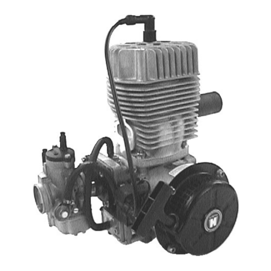
- Page 7 GH F33 BDA Illustration 1.1.1-2 (Engine F 33 B) 1.1.2 Description of the fuel mixture system 1.1.2-1 Variable jet carburettor The fuel mixture system (Illus. 1.1.2-1) of the engine F 33 A consists of a variable jet carburettor. The carburettor is linked with intake window and the inlet diaphragm of crankcase by a rubber flange.
- Page 8 GH F33 BDA 1.1.2.2 Diaphragm carburettor The fuel mixture system (picture 1.1.2-2) of the engine F33 B consists of a diaphragm carburettor. The carburettor is linked with intake window and the inlet diaphragm of crankcase by an aluminium flange. In this occasion the aluminium flange is screwed by cylinder screws and locking discs at the cylinder and the carburettor is fixed at the aluminium flange by insulated part.
-
Page 9: Engine Installation
GH F33 BDA Illustration 1.1.3-2 (Dual ignition lighting system) 1.2 Installation 1.2.1 Engine installation The four threads (M 8) for engine mounting at engine F33 A (Illus. 1.2.1-1) are positioned at bottom side of crankcase. Illustration 1.2.1-1 (Attachment threads) The engine mounting should be conditioned in that way, that transferred impulse from the engine to the mounting will be taken over as high / wide as possible. - Page 10 GH F33 BDA The damping of the mounting should be chosen as hard as possible, because engine could sway/ swing itself with damped mounting which is too smooth. This leads to problems with the fuel mixture (i.e. foam up of the fuel, uncontrolled centrifuge of the fuel pump diaphragm) and so to an unsafe running of the engine.
- Page 11 GH F33 BDA Pay attention that in standing position of the diaphragm pump the outlet is at the top. Place fuel connecting piece is perceptible by marking (→)on the case. The centrically connection the diaphragm pump is an impulse connection. The impulse line from the crankcase to the diaphragm pump should be as short as possible.
- Page 12 GH F33 BDA 1.2.6 Adjustment of the idle fuel mixture Screw for idle is adjusted by Göbler Hirthmotoren before delivery of the engine and should not be twisted. As standard the screw is opened with 1,5 rotations. For readjusting the screw, tie it clockwise till screw is tight/ fixed (only tie slight against resistance) then turn off the screw anti-clockwise with 1,5 rotations.
- Page 13 GH F33 BDA 1.3.1 CHT (Cylinder head temperature) Cylinder head temperature (see Table 1.5-1) is measured at fitting beneath the spark plug. Hereby a ring-shaped thermocouple element is screwed in beneath the spark plug. The positioning of the thermocouple element is very important. The connecting cable of the thermocouple element should be conducted upwards in the way that the cooling air does not blow at the connection from the cable to the ring-shaped measure element.
- Page 14 Electronic ignition system, single or dual Generator 50 W, 12 V (Option) Spark plugs single ignition 023.22 (Hirth), B 8 HS (NGK), W 24 FS-U (N D) Spark plugs double ignition 023.26 (Hirth), C 8 HSA (NGK), U 24 FS-U (N D) Ignition timing 16°...
- Page 15 GH F33 BDA 1.6 Installation sketch 2 3 0 7 4 , 5 M 8 ( 4 x ) 1 3 1 , 5 2 9 9 , 5 Stand: 02.02.05 DOC_F33_B_E_0.01...
- Page 16 GH F33 BDA Chapter 2 Operating of the Engine 2.1 General ly The absolute attention of this chapter is essential for a long, economic and satisfactory operating of the engine. ONLY USE BRAND 2 STROKE-OIL AND THE PRESCRIBED FUEL (MIXTURE RATIO 1:50).
- Page 17 GH F33 BDA tighten up the cylinder head screws for reasons of safety tighten up the spark plugs for reasons of safety viewing examination (leaking, unassembled nuts/ screws,…) Attention ! It is recommended to check the following items before every engine running for reasons of safety: Starter (checking of connections, fixings and condition;...
- Page 18 GH F33 BDA 2. run up of engine in a speed range where centrifugal clutch is positioned without fixed gearing. Because in this case the run up range is very slow, the time of run up should be longer. Attention ! If the warm up or other engine operation is carried out in the range where the clutch engages, the result may be increased wear on the surface, glazing of the coating, or overheating of the clutch.
-
Page 19: Maintenance
GH F33 BDA Chapter 3 Maintenance 3.1 Generally 3.1.1 Index This chapter contains main instruction for technically qualified personnel to carry out minor inspections and repairs, such as: Periodical inspections of engine Maintenance of engine components Trouble shooting 3.1.2 Tools , special tools and torques Description and sizes of tools are indicated in metrical system and can be purchased in special shops. - Page 20 GH F33 BDA 1. Air filter – checking of condition and bolting 2. Starter – checking of condition and bolting 3. Ignition component – checking of condition, mounting and junction/ connection 4. Crank case and cylinders – checking of leakage, condition and bolting 5.
- Page 21 GH F33 BDA Multiple dis valve 058.9 3.4 Maintenance Instructions 3.4.1 variable jet and diaphragm carburettor Carburettor is jetted from Göbler Hirthmotoren so that thermical secured running is guaranteed. As interference on jets could lead to overheating and damage of engine, this should be left off.
- Page 22 GH F33 BDA 3.4.3 Fuel and Pulse Lines 3.4.3.1 Inspection of Fuel Lines Check the fuel line between the fuel diaphragm pump, carburettor and fuel tank for leakings and/ or damages. Leaking and/or damaged fuel lines have to removed immediately. 3.4.3.2 pulse line check Check pulse line between the negative-pressure nipple at crankcase and the pulse connection of the fuel diaphragm pump for leakings and / or damages.
- Page 23 GH F33 BDA 3.4.5.1 installation and deinstallation of cylinder head For deinstallation of cylinder head, the spark plug connector and spark plug has to be removed as mentioned before. Untie and turn off the eight cylinder head – clamping bolt by hexagon head socket wrench.
- Page 24 GH F33 BDA 3.5.2 Engine does not run at idle speed Cause : -Idle speed adjusted too low Solution: -On the carburettor, screw the idle stop screw in Cause: -Idle speed adjusted too high Solution: -On the carburetor, screw the idle stop screw out Cause: -Idle running mixture adjusted wrong Solution:...
- Page 25 GH F33 BDA Solution: -Send engine to Göbler-Hirthmotoren or authorized Hirth supplier Cause: -wrong ignition timing Solution: -adjust ignition timing -send engine to Göbler-Hirthmotoren or authorized supplier 3.5.5 cylinder Head Temperature is too high Cause: -engine gets less cooling air...
- Page 26 The 6 following wiring diagrams are referring to single and dual ignition systems with and without generator coil, just as without and with electric starter Attention: Read also the Hirth Information 0065 „Additional Information on voltage supply and ignition system” Stand: 02.02.05 DOC_F33_B_E_0.01...
- Page 27 GH F33 BDA r o t s c h w a r z r e d b l a c k Z ü n d u n g Z ü n d s p u l e I g n i t i o n I g n i t i o n c o i l 0 2 0 .
- Page 28 GH F33 BDA r o t s c h w a r z r e d b l a c k Z ü n d u n g Z ü n d s p u l e Z ü n d s p u l e I g n i t i o n I g n i t i o n c o i l I g n i t i o n c o i l...
- Page 29 GH F33 BDA Dieser Schaltplan versteht sich als Verlegungsvorschlag Name This wiring diagram is to be considered as a proposal for wiring Gezeichnet: 07.01.99 Rögele Geprüft: Leitungsquerschnitt allgemein: 1,5 mm 07.01.99 Rögele General size of line wire: 1,5 mm Schaltplan – Doppelzündung Wiring diagram –...
- Page 30 GH F33 BDA Dieser Schaltplan versteht sich als Verlegungsvorschlag Name This wiring diagram is to be considered as a proposal for wiring Gezeichnet: 07.01.99 Rögele Leitungsquerschnitt allgemein: 1,5 mm Geprüft: 07.01.99 Rögele General size of line wire: 1,5 mm Schaltplan – EZ mit Generatorspule Wiring diagram –...
- Page 31 GH F33 BDA Dieser Schaltplan versteht sich als Verlegungsvorschlag Name This wiring diagram is to be considered as a proposal for wiring Gezeichnet: 12.01.99 Rögele Leitungsquerschnitt allgemein: 1,5 mm Geprüft: 12.01.99 Rögele General size of line wire: 1,5 mm Schaltplan – DZ mit Generatorspule Wiring diagram –...
- Page 32 GH F33 BDA Dieser Schaltplan versteht sich als Verlegungsvorschlag Name Gezeichnet: This wiring diagram is to be considered as a proposal for wiring 12.01.99 Rögele Leitungsquerschnitt allgemein: 1,5 mm Geprüft: 12.01.99 Rögele General size of line wire: 1,5 mm Schaltplan – EZ mit Gen.-spule + E-St. Leitungsquerschnitt von/zu E-Starter: 16 mm Wiring diagram –...
- Page 33 GH F33 BDA gelb yellow Dieser Schaltplan versteht sich als Verlegungsvorschlag Name This wiring diagram is to be considered as a proposal for wiring Gezeichnet: 12.01.99 Rögele Leitungsquerschnitt allgemein: 1,5 mm Geprüft: 12.01.99 Rögele General size of line wire: 1,5 mm Schaltplan –...
Need help?
Do you have a question about the F 33 A/B and is the answer not in the manual?
Questions and answers