Table of Contents
Advertisement
Quick Links
INSTALLATION AND PROGRAMMING
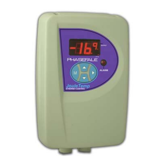
Phasefale's TC1
INDEX
1. Installation
2a. Advanced Programming Options
2b. A Programming Example
7. Alphabetical Table of Indications
General Overview and Introduction
Phasefale's TC1 is a single stage
(on/off) temperature controller with
defrost capabilities and is simple to
set up and operate. The temperature is
shown on the LED display. If cooling
or heating operations are occurring a
point is displayed at the end of the
temperature display.
During defrost,
dF is displayed. The programmed
settings may be viewed by pressing
and holding the
button for 2
seconds. A (display only) temperature
alarm is indicated by the flashing of
the temperature display.
The TC1 is a simplified version of the
TACm
control
which
sophisticated
alarm
facilities
addition to the control capabilities of
the TC1 detailed here.
1. INSTALLATION
Enclosure Installation
The Enclosure can be mounted in any
position, and is splash proof. Mount
the base and fit two of the mounting
screws in the lid. The lid can then be
hinged out to allow the electrical
connections to be made.
Temperature Sensor (M Probe)
Installation
The temperature sensor is an NTC
thermistor
of
extreme
(0.2°C), and it has a non-linear
resistance-temperature
characteristic
(see chart below). It is ideally mounted
in a position where refrigerated air is
circulating.
At least 150mm of the sensor cable
needs to be in the refrigerated space
to
ensure
accurate
sensing.
P:\1doc\pman\cinst\TC156.DOC
If the sensor cable is open or short
circuit, the TC1 will display Er to
indicate the fault.
The sensor cable is double insulated
and therefore does not need to be
enclosed in a conduit. There is no
polarity to the sensor connection. It
may be extended up to 100 metres by
joining an extra cable (use double
insulated cable) but the join must be
well insulated and away from any dirt
or moisture.
Dirt or moisture at the join will reduce
the resistance of the probe and result in
4 00 k
3 00 k
2 00 k
1 00 k
0 k
R e s is ta nc e v s T em p . (C e ls iu s)
E x te nd M P ro b e to 10 0m .
us in g H e ats hrink on joins
a higher temperature reading than
includes
normal.
in
Electrical Installation
Refer also to the electrical wiring
diagram for connection details. The
Active supply to the unit should be
fused with a maximum rating of 10A.
The control output is rated at 10A
resistive. Motors larger than 1 HP
MUST be switched via a relay or
contactor (available from Phasefale).
If the mdPCB option for heater and
fan outputs is to be fitted, follow the
instructions supplied with it.
TC1 is not supplied with a complog
interface.
Installation Self-Test
Press
accuracy
The TC1 automatically cycles its
outputs in the following sequence:
Display
CO/CF
LO/LF
dO/dF
temperature
HO/HF
FO/FF
R es is tan ce
T D e g C
-20
-10
0
1 0
M P ro b e-
and
together for 5 seconds.
Action
sec.
Control On&Off
10/4
nil
4/4
nil
4/4
Heater On&Off
4/4
Fan On&Off
4/4
Page 1 of 4 Q1 2008
2. PROGRAMMING
The basic programming steps are:
• "Unlock" the TC1 permanent
memory for programming
• Select the setting to be adjusted.
• Alter the setting to your desired
value.
• Store the changed value.
• Return to normal operation.
a) To unlock the TC1 and alter the
settings, press
and
seconds. UL will be displayed to
indicate that the system is unlocked.
b) After the TC1 is unlocked press
until the setting you wish to alter is
displayed. The settings and values are
displayed in the table below:
Sett-
De-
Display
ing
fault
SP
0.0
Control Setpoint °C
2 0
(-35 ~ +55°C)
dI
Ec
Differential Temp °C
0.5~5°C, Ec: economy
AH
13
High Alarm Temp. °C
(-30~ +60°C)
AL
-5.0
Low Alarm Temp. °C
(-40~+50°C)
At
90
Alarm Time Delay
(0~99 minutes)
nd
1
Number of defrosts per
24hr (0~6)
dd
30
Defrost
(1~99minutes)
c) After the setting to be adjusted is
displayed,
you
decrease the setting by pressing
until the numerical value required is
displayed.
d) To store the changed value, press
the
keypad. The new value is now
stored indefinitely and will remain
during power loss.
e) If no keypad is pressed for 60
seconds the TC1 will once again lock
itself and further alterations will be
disallowed until unlocked again. This
will also occur if the
during the programming operation.
Remember! you must store each
altered value using
2a.
ADVANCED
PROGRAMMING OPTIONS
A further series of functions and
commands can be accessed during the
together for 5
adjustment
range
duration
can
increase
or
or
key is pressed
[AAmenu]
Issue 3
Advertisement
Table of Contents

Summary of Contents for Phasefale TC1
- Page 1 7. Alphabetical Table of Indications well insulated and away from any dirt 8. TC1 Wiring Diagram or moisture. a) To unlock the TC1 and alter the Dirt or moisture at the join will reduce General Overview and Introduction settings, press...
- Page 2 As we are energy conscious, we will normal operating limits. It may be The TC1 is now ready for operation. use the economy mode of operation. cleared by pressing the button.
- Page 3 TACm, these units are the latest in control equipment from Australia’s favourite cool room control manufacturer! Check our website below or call Phasefale to find out more about this amazing control. JouleTemp is built to the same high standards as TACm.
- Page 4 Electric defrost HF Heater OFF UL programming unlocked dF Defrost or Dialler OFF H0 Heater ON Indications in italics not applicable to TC1 dg Gas defrost LF Light OFF Def is the default setting 10A RES. MAX 1 Hp...
Need help?
Do you have a question about the TC1 and is the answer not in the manual?
Questions and answers