Table of Contents
Advertisement
Quick Links
HCS9000B / HCS9200B
Composite Repair Set; Hot Bonder
Operation and Maintenance Manual
with
Illustrated Parts Catalog
This Technical Manual Applies to HCS9000B and HCS9200B Revision 16
Composite Repair Sets (Hot Bonders) with Serial Numbers listed below:
Serial Numbers – 1611XXXX and Subsequent
To buy, sell, rent or trade-in this product please click on the link below:
http://www.avionteq.com/Heatcon-HCS9200B-Single-Dual-Zone-Hot-bonder-Composite-Bonding-Repair-System.aspx
www.avionteq.com
HCS9000B/HCS9200B-OMI-405
18 November 2013
Advertisement
Table of Contents

Subscribe to Our Youtube Channel
Related Manuals for AvionTEq HEATCON HCS9000B

Summary of Contents for AvionTEq HEATCON HCS9000B
- Page 1 This Technical Manual Applies to HCS9000B and HCS9200B Revision 16 Composite Repair Sets (Hot Bonders) with Serial Numbers listed below: Serial Numbers – 1611XXXX and Subsequent To buy, sell, rent or trade-in this product please click on the link below: http://www.avionteq.com/Heatcon-HCS9200B-Single-Dual-Zone-Hot-bonder-Composite-Bonding-Repair-System.aspx www.avionteq.com HCS9000B/HCS9200B-OMI-405 18 November 2013...
- Page 3 HCS9000B/HCS9200B Proprietary Notice Hot Bonder/Controller Manual Title: "HCS9000B/HCS9200B Operation and Maintenance Manual with Illustrated Parts Catalog" Copyright 24 October 2011 All rights reserved. No part of this publication may be reproduced, transmitted, transcribed, stored on a retrieval system, or translated into any language in any form by any means without the expressed written ...
- Page 4 Change Record HCS9000B/HCS9200B Hot Bonder/Controller CHANGE PAGE RECORD NOTE: A vertical line in the outer margins of the page indicates the portions of this manual affected by changes. Dates of issue for the original and changed pages are: Original – 24 October 2011 Revision 1 –...
-
Page 5: Table Of Contents
HCS9000C/HCS9200C Front Matter Hot Bonder/Controller TABLE OF CONTENTS TABLE OF CONTENTS ............................ I LIST OF FIGURES ............................III LIST OF TABLES ............................IV ABBREVIATIONS AND ACRONYMS ......................V WARNINGS AND CAUTIONS ........................VIII TECHNICAL SPECIFICATIONS ........................X CHAPTER 1 — GENERAL ........................... 1 Introduction ............................ - Page 6 Reference Pages HCS9000B/HCS9200B Hot Bonder/Controller 3.4.4.2 Run Program Screen ......................... 34 3.4.4.3 8 Step Cure Configuration ......................... 35 3.4.5 Graph Screen ............................ 36 3.4.6 Precure Operational Test Screen ...................... 37 Changing an Active Program ......................39 3.6.1 Slave Mode ............................39 3.6.2 20 TC Mode ............................
- Page 7 HCS9000C/HCS9200C Front Matter Hot Bonder/Controller LIST OF FIGURES Figure Title Page HCS9200B Display Screen Under Network Control ............... 7 Network Port Location (HCS9000B) ....................8 Network Controller (HCS9300NW) ....................8 Controls and Indicators HCS9000B - Single Zone ................. 9 Controls and Indicators HCS9200B - Dual Zone ................11 Bonder Connection Diagram ......................
- Page 8 Reference Pages HCS9000B/HCS9200B Hot Bonder/Controller LIST OF TABLES Table Title Page Technical Specification ........................viii Controls and Indicators HCS9000B - Single Zone ................. 10 Controls and Indicators HCS9200B - Dual Zone ................11 Alarm Popup Windows ........................42 Equipment Required for Testing..................... 54 Troubleshooting Guide ........................
-
Page 9: Abbreviations And Acronyms
HCS9000B/HCS9200B Abbreviations and Acronyms Hot Bonder/Controller ABBREVIATIONS AND ACRONYMS ASCII American Standard Code for Information Interchange Alternating Current Binary digit (one bit of data - either 0 or 1) CAGE Contractor and Government Entity (Code) Circuit Breaker Circuit Card Assembly Cubic feet per minute Communication COTS... -
Page 10: Warnings And Cautions
Warnings and Cautions HCS9000B/HCS9200B Hot Bonder/Controller WARNINGS AND CAUTIONS WARNINGS and CAUTIONS are used throughout this manual to alert personnel to the hazards associated with the operation and use of the HCS9000B/HCS9200B Composite Repair Set (Hot Bonder), and with the materials and processes used to repair composite structures. - Page 11 HCS9000B/HCS9200B Warnings and Cautions Hot Bonder/Controller USE CAUTION WHEN REMOVING THE CHASSIS FROM CASE. THE CHASSIS IS ATTACHED TO THE CASE BY THE VACUUM EXHAUST HOSE(S). ENSURE THAT VACUUM HOSES ARE DISCONNECTED AND ALL CABLES AND WIRES ARE CLEAR OF THE CASE FLANGE WHEN THE CHASSIS IS REMOVED.
-
Page 12: Technical Specifications
Technical Specifications HCS9000B/HCS9200B Hot Bonder/Controller TECHNICAL SPECIFICATIONS Table 1. Technical Specifications FEATURE HCS9000B HCS9200B 90 – 264 Volts AC, 90 – 264 Volts AC, Power: (Voltage) 47 – 63; 400 Hz 47 – 63; 400 Hz Maximum Input: 30 Amps Maximum Input: 30 Amps (per zone) Current: (Amperage) Maximum Output 30 Amps... -
Page 13: Chapter 1 - General
HCS9000B/HCS9200B Functional Description Hot Bonder/Controller CHAPTER 1 GENERAL INTRODUCTION The HCS9000B/HCS9200B Composite Repair Set (Hot Bonder) is a computer monitored and controlled electrical heating composite repair system with multiple sensor inputs and various graphical status display screens with complete process documentation printout. The HCS9000B is a single zone unit and the HCS9200B is a dual zone unit. -
Page 14: Quick Start Guide
General HCS9000B/HCS9200B Hot Bonder/Controller QUICK START GUIDE The following is a brief explanation of a simple cure scenario to familiarize a new user with the basic operation of the bonder. More detailed explanations of bonder functions and theory of operation are available in Chapter 3, Operation. - Page 15 HCS9000B/HCS9200B Functional Description Hot Bonder/Controller Plug the TCs from the vacuum bag repair area into the TC jacks on the bonder faceplate. Energize the bonder by placing the POWER rocker power switch to the “ON” position. The bonder will present the WELCOME screen. Keypad instructions are displayed at the bottom of each screen. The WELCOME screen provides the software version installed in the unit and the Calibration Due Date.
-
Page 16: Chapter 2 - Functional Description
Functional Description HCS9000B/HCS9200B Hot Bonder/Controller CHAPTER 2 FUNCTIONAL DESCRIPTION AC POWER CONTROL Alternating Current (AC) source power is brought into the hot bonder through the front panel input power connector(s). AC power for the control circuitry is then routed through the front panel power switch to the Direct Current (DC) power supply (ref. -
Page 17: Printer
HCS9000B/HCS9200B Functional Description Hot Bonder/Controller PRINTER The HCS9000B/HCS9200B series Hot Bonders employ dot matrix, impact type printers to produce a hard copy record of the repair process. The HCS9200B has a printer for each zone. The printers are self- contained units mounted in the front panel assembly. The printer is interfaced to the CPU Carrier CCA parallel ports. -
Page 18: Proportional, Integral And Derivative (Pid) Control
Functional Description HCS9000B/HCS9200B Hot Bonder/Controller PROPORTIONAL, INTEGRAL AND DERIVATIVE (PID) CONTROL 2.7.1 PID CONTROL BASICS The heat control system used in the hot bonders is referred to as a Closed Loop System. This means that the heat output is controlled by feedback from the input thermocouples, which are in contact with the heat load. -
Page 19: Derivative
HCS9000B/HCS9200B Functional Description Hot Bonder/Controller DERIVATIVE Derivative is the “D” in PID, is more commonly known as “rate”. The function of 2.7.4 rate is to prevent overshoot of the setpoint by the process. It does this by slowing the rate of approach of the actual temperature to the setpoint. - Page 20 Functional Description HCS9000B/HCS9200B Hot Bonder/Controller Figure 2-2. Network Port Location (HCS9000B) Figure 2-3. Network Controller (HCS9300NW) ® HEATCON COMPOSITE SYSTEMS HCS9000B/HCS9200B-OMI-405...
-
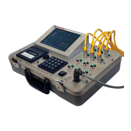
Page 21: Chapter 3 - Operation
HCS9000B/HCS9200B Operation Hot Bonder/Controller CHAPTER 3 OPERATION CONTROLS AND INDICATORS All controls and indicators required to operate the HCS9000B/HCS9200B Composite Repair Set (Hot Bonder) are available from the faceplate on front of the unit. The controls and indicators for the HCS9000B and the HCS9200B are identical, except that the HCS9200B has two separate zones. - Page 22 Operation HCS9000B/HCS9200B Hot Bonder/Controller Table 3-1. Controls and Indicators HCS9000B - Single Zone Index Control/Indicator Function LCD Display Panel Viewing of operator interface screens/information Output Power LED (Green) Flashes in proportion to the rate of power output to circuit. Thermocouple Jacks 1-5 Jacks for plugging-in thermocouples No.
- Page 23 HCS9000B/HCS9200B Operation Hot Bonder/Controller Figure 3-2. Controls and Indicators HCS9200B - Dual Zone Table 3-2. Controls and Indicators HCS9200B - Dual Zone Index Control/Indicator Function Flashes in proportion to the rate of power output to Output Power LED (Green). Zone 1 circuit LCD Display Panel Viewing of operator interface screens/information...
-
Page 24: Equipment Setup And Power-On
Operation HCS9000B/HCS9200B Hot Bonder/Controller Table 3-2. Controls and Indicators HCS9200B - Dual Zone (Cont’d) Index Control/Indicator Function Printer Paper Feed Pushbutton Press to advance paper. Release to stop. Switch, Zone 2 Printer Assembly, Zone 2 Prints cure program data. Adjustable audible alarm. Sounds when temperature Alarm or vacuum condition in the repair is outside (+/-) cure parameters, or other alarms occur. - Page 25 HCS9000B/HCS9200B Operation Hot Bonder/Controller c. Locate and connect power cable(s) to unit. Zone 1 is the primary zone and must have input power applied to run the computer and operator interface screens as well as Zone 1 output. d. Locate and connect vacuum hoses. (1) Connect one vacuum hose end to the VACUUM OUT port on the bonder and the other end to a vacuum through-bag connector (sniffer) in vacuum bag layup.
- Page 26 Operation HCS9000B/HCS9200B Hot Bonder/Controller Input Power Output Power Box Electric Vacuum Input Power Output Power Box Figure 3-3. Bonder Connection Diagram Receptacle Receptacle Pump Power Receptacle Receptacle Vacuum Out Vacuum Port Monitor Port Vacuum Monitor Port Vacuum Out Port Shop Air Input Port Zone 2 TC Jacks...
-
Page 27: Power-On Procedure
HCS9000B/HCS9200B Operation Hot Bonder/Controller 3.1.2 POWER-ON PROCEDURE WARNING BEFORE CONNECTING ELECTRICAL POWER TO THE HOT BONDER/CONTROLLER, ENSURE THE FACILITY SOURCE POWER IS RATED FOR THE REQUIRED AMPERAGE AND THAT THE HOT BONDER/CONTROLLER IS EQUIPPED WITH A POWER CABLE AND PLUG CAPABLE OF THAT AMPERAGE. (REFER TO LOCAL CODES) To apply power to the HCS9000B/HCS9200B Hot Bonder, after completing the Equipment Setup as described in par. -
Page 28: Security Password Protection (Option)
Operation HCS9000B/HCS9200B Hot Bonder/Controller SECURITY PASSWORD PROTECTION (OPTION) The HCS9000B/HCS9200B Hot Bonder may be equipped with password protection as an option. When a new machine is initially powered-up, a prompt will be displayed that instructs the operator to enter a password. -
Page 29: Password Assignment
HCS9000B/HCS9200B Operation Hot Bonder/Controller 3.3.2 PASSWORD ASSIGNMENT There are 20 password entries available in the system. The SUPERVISOR assigns passwords by accessing the PASSWORD SETUP SCREEN (Figure 3-6), entering a password number (1 through 20) and then following the prompts for data entry. More than one supervisor password may be active at the same time, but is not recommended. -
Page 30: Operator Graphic User Interface Screens
Operation HCS9000B/HCS9200B Hot Bonder/Controller OPERATOR GRAPHIC USER INTERFACE SCREENS The Graphic User Interface (GUI) screens provide a visual display for inputting, modifying, and observing information into the computer system to operate the HCS9000B/HCS9200B. A series of primary screens and secondary operator interface screens, sub-screens, windows and popup menus provide a graphic and text presentation that is extremely user friendly. -
Page 31: Main Menu And Status Monitor Screen
HCS9000B/HCS9200B Operation Hot Bonder/Controller 3.4.2 MAIN MENU AND STATUS MONITOR SCREEN The MAIN MENU AND STATUS MONITOR Screen (Figure 3-8) is the first screen displayed after starting-up the unit and pressing "ESC" from the WELCOME Screen. This screen can be accessed from any other screen by pressing the "ESC"... - Page 32 Operation HCS9000B/HCS9200B Hot Bonder/Controller HEATCON COMPOSITE SYSTEMS MAIN MENU & STATUS MONITOR SCREEN MONITOR - ZONE 1 MONITOR - ZONE 2 TC 1 TC 1 TC 2 TC 2 TC 3 OPEN TC 3 OPEN TC 4 OPEN TC 4 OPEN TC 5 OPEN...
-
Page 33: User Settings Screen
HCS9000B/HCS9200B Operation Hot Bonder/Controller 3.4.3 USER SETTINGS SCREEN The USER SETTINGS Screen (Figure 3-9) is accessed by pressing "2" from the MAIN MENU AND STATUS MONITOR Screen. This screen provides a menu to establish thermocouple control settings, printer options, set the time and date, and select the values for displaying temperature and vacuum. a. -
Page 34: Temperature Control Modes Screen
Operation HCS9000B/HCS9200B Hot Bonder/Controller 3.4.3.1 TEMPERATURE CONTROL MODES SCREEN The TEMPERATURE CONTROL MODES Screen (Figure 3-10) is accessed by pressing "1" from the USER SETTINGS Screen. From this screen information is entered which establishes control methods for cure processing. The available modes for each zone include: Average of All Thermocouples Highest Thermocouple Lowest Thermocouple... -
Page 35: Thermocouple Mode Options Screen
HCS9000B/HCS9200B Operation Hot Bonder/Controller 3.4.3.2 THERMOCOUPLE MODE OPTIONS SCREEN The THERMOCOUPLE MODE OPTIONS Screen (Figure 3-11) is accessed by pressing "2" from the USER SETTINGS Screen. From this screen the options are selected for each of the TCs to be included in the cure as controlling or Monitoring TCs and if they are included in the printout or not. -
Page 36: Printer Options Screen
Operation HCS9000B/HCS9200B Hot Bonder/Controller THERMOCOUPLE CONTROL AND DISPLAY MODES TC NUMBER 1 ZONE 1 CONTROL AND PRINT MONITOR AND PRINT MONITOR AND NO PRINT USE NUMBER KEYS TO SELECT OPTIONS PRESS ENT TO SAVE CHANGES AND RETURN TO PREVIOUS MENU PRESS ESC TO CANCEL AND RETURN TO PREVIOUS MENU Figure 3-12. -
Page 37: Display Options Screen
HCS9000B/HCS9200B Operation Hot Bonder/Controller PRINTER OPTIONS ZONE 1 PRINTER ON ZONE 1 PRINTER OFF ZONE 2 PRINTER ON ZONE 2 PRINTER OFF PRINT MODE: SUMMARY LINE PRINT PRINT MODE: ALL THERMOCOUPLE READINGS PRINT INTERVAL 5 MINUTES USE NUMBER KEYS TO SELECT OPTIONS PRESS ENT TO SAVE CHANGES AND RETURN TO PREVIOUS MENU PRESS ESC TO CANCEL AND RETURN TO PREVIOUS MENU Figure 3-13. -
Page 38: Segment Completion Signal Screen
Operation HCS9000B/HCS9200B Hot Bonder/Controller DISPLAY OPTIONS TEMPERATURE DEGREES F TEMPERATURE DEGREES C VACUUM LEVEL - IN/HG VACUUM LEVEL - MBARS VACUUM LEVEL - KPA PRESS ↑ ↓ TO ADJUST SCREEN BRIGHTNESS 100% THE BRIGHTNESS MAY ALSO BE ADJUSTED FROM THE WELCOME OR MAIN MENU SCREENS BY USING ↑... -
Page 39: Usb Import & Export Options Screen
HCS9000B/HCS9200B Operation Hot Bonder/Controller SEGMENT COMPLETION SIGNAL SEGMENT COMPLETION SIGNAL - ON SEGMENT COMPLETION SIGNAL - OFF USE NUMBER KEYS TO SELECT OPTIONS PRESS ENT TO SAVE CHANGES AND RETURN TO PREVIOUS MENU PRESS ESC TO CANCEL AND RETURN TO PREVIOUS MENU Figure 3-15. -
Page 40: Import &Export Cure Program Library Screen
Operation HCS9000B/HCS9200B Hot Bonder/Controller USB IMPORT & EXPORT OPTIONS ASK BEFORE OVERWRITING OLDEST CURE FILE DO NOT ASK BEFORE OVERWRITING OLDEST CURE FILE EXPORT / IMPORT CURE PROGRAM (PROFILE) LIBRARY USE NUMBER KEYS TO SELECT OPTIONS PRESS ENT TO SAVE CHANGES AND RETURN TO PREVIOUS MENU PRESS ESC TO CANCEL AND RETURN TO PREVIOUS MENU Figure 3-16. -
Page 41: Date And Time Settings Screen
HCS9000B/HCS9200B Operation Hot Bonder/Controller IMPORT & EXPORT CURE PROGRAM (PROFILE) LIBRARY EXPORT CURE PROGRAM LIBRARY TO USB FLASH DRIVE IMPORT CURE PROGRAM LIBRARY FROM USB FLASH DRIVE USE NUMBER KEYS TO SELECT OPTIONS PRESS ESC TO RETURN TO PREVIOUS MENU Figure 3-17. -
Page 42: 10Advanced Options Screen
Operation HCS9000B/HCS9200B Hot Bonder/Controller 3.4.3.10 ADVANCED SETTINGS SCREEN The ADVANCED SETTINGS Screen (Figure 3-19) is accessed by pressing "8" (Advanced Settings) from the USER SETTINGS Screen. The Advanced Settings Menu is only available when enabled by the factory. If enabled, not all options may be available depending on system configuration. ADVANCED SETTINGS ALL TC RISE PRE-CURE LAYUP TEST ANY TC RISE PRE-CURE LAYUP TEST... -
Page 43: 11Alternate Pid Settings
HCS9000B/HCS9200B Operation Hot Bonder/Controller 3.4.3.11 ALTERNATE PID SETTINGS The ALTERNATE PID SETTINGS Screen (Figure 3-20) is accessed by pressing "9" (Edit Alternate PID Values) from the ADVANCED SETTINGS Screen. The Alternate PID Settings Menu is only available when enabled by the factory. PID Values are entered for each zone; Proportional Bandwidth, Integral, and Derivative. -
Page 44: Program Selection Screen
Operation HCS9000B/HCS9200B Hot Bonder/Controller 3.4.4 PROGRAM SELECTION SCREEN The PROGRAM SELECTION Screen (Figure 3-21) is accessed by pressing "1" from the MAIN MENU AND STATUS MONITOR Screen. From the PROGRAM SELECTION Screen, programs may be RUN, ENTERED, EDITED or DELETED. This screen displays the 30 programs that are stored in memory. Each program is numbered 1 thru 30 and has space for entering program names up to 20 characters long. -
Page 45: Edit Program Screen
HCS9000B/HCS9200B Operation Hot Bonder/Controller 3.4.4.1 EDIT PROGRAM SCREEN The EDIT PROGRAM Screen (Figure 3-22) is displayed by selecting a program number on the PROGRAM SELECTION screen that is empty, or by selecting an existing program and pressing ‘2’ to edit the program. The edit screen can also be accessed by selecting "EDIT THE PROGRAM"... -
Page 46: Run Program Screen
Operation HCS9000B/HCS9200B Hot Bonder/Controller 3.4.4.2 RUN PROGRAM SCREEN To access the RUN PROGRAM Screen (Figure 3-23), press "1" from the MAIN MENU AND STATUS MONITOR Screen. Select the desired program to be RUN by entering the program number, or selecting the program with the cursor and pressing “ENT”. -
Page 47: Step Cure Configuration
HCS9000B/HCS9200B Operation Hot Bonder/Controller 3.4.4.3 8 STEP CURE CONFIGURATION EDIT PROGRAM NAME: BMS5-129-250F STEP RAMP RATE DWELL (F / MIN) TEMP (F) TIME (MIN) FINAL LOW VACUUM ALARM: 22 In / Hg RAMP HIGH LIMIT (+ / - DEV): 20 F RAMP LOW LIMIT (+ / - DEVI): 20 F DWELL HIGH LIMIT (+ / - DEV):... -
Page 48: Graph Screen
Operation HCS9000B/HCS9200B Hot Bonder/Controller 3.4.5 GRAPH SCREEN The GRAPH SCREEN (Figure 3-26) presents a graphic representation of the cure. The GRAPH SCREEN is accessed from the MAIN MENU & STATUS MONITOR SCREEN by pressing "3" to view the Zone 1 Graph or "4"... -
Page 49: Precure Operational Test Screen
HCS9000B/HCS9200B Operation Hot Bonder/Controller ZONE 2 READY PROGRAM OPERATIONAL TEST 2 PART #: SERIAL #: OPERATOR: OPEN OPEN OPEN OPEN OPEN OPEN OPEN TC10 OPEN 0 IN 10 MINUTES PER DIVISION MODE RAMP RATE AVERAGE TC CONTROL SETPOINT USE ↑ ↓ TO MOVE CURSOR ACTUAL TOTAL TIME 'ENT' TO TAKE ACTION... - Page 50 Operation HCS9000B/HCS9200B Hot Bonder/Controller d. The 4-second power application should produce a heat rise in the cure lay-up. The connected TC readings are monitored to detect any heat rise. The system allows 14 seconds for all of the TC readings to rise at least 2 F.
-
Page 51: Changing An Active Program
HCS9000B/HCS9200B Operation Hot Bonder/Controller CHANGING AN ACTIVE PROGRAM When a program is selected from the library and executed, a temporary working copy of that program is stored in memory. When changes are made to the active program by selecting EDIT THE PROGRAM on the graph screen, these changes affect only the cure in progress and not the original stored program. -
Page 52: Tc Mode
Operation HCS9000B/HCS9200B Hot Bonder/Controller 3.6.2 20 TC MODE The purpose of 20 TC operation is to allow Zone 1 to operate one cure program using all TCs from both zones. A single output is used (zone 1), but all available thermocouples are applied to a single zone cure. This is used in situations where only a single zone of control is needed, but more than 10 Thermocouples are required. -
Page 53: Alarms
HCS9000B/HCS9200B Operation Hot Bonder/Controller ALARMS The HCS9000B/HCS9200B has installed in the faceplate an adjustable volume, audible alarm. The alarm provides an audible indication that something in the cure process is outside of parameters established in the programmed cure. The alarm parameters are set up as deviation alarms, not absolute alarms. Conditions that can cause an alarm are;... - Page 54 Operation HCS9000B/HCS9200B Hot Bonder/Controller When an alarm condition is encountered, a popup window is presented in the lower right-hand corner of the currently displayed screen. This popup window displays the alarm condition and states how to silence the alarm, and also contains a warning that the condition is not corrected when the alarm is silenced. The box and text are displayed in red.
-
Page 55: Max Power Warning & Alarm
HCS9000B/HCS9200B Operation Hot Bonder/Controller 3.7.1 MAX OUTPUT POWER WARNING & ALARM The Maximum Output Power Warning (Figure 3-30) is displayed if the actual temperature falls below the setpoint temperature and the power output to the load fails to raise the temperature to the setpoint. If the bonder sends output power to the load at 90% duty cycle or greater for 60 seconds and a rise in temperature of at least 1 ºF is not detected, the “MAX OUTPUT POWER”... - Page 56 Operation HCS9000B/HCS9200B Hot Bonder/Controller WARNING DISABLING THE MAX POWER ALARM WILL ALLOW THE BONDER TO APPLY OUTPUT TO THE LOAD WITHOUT MONITORING. THIS COULD RESULT IN AN OVERHEAT CONDITION IF THE SENSORS ARE IMPROPERLY PLACED ON THE REPAIR. ZONE 1 ALARM - RAMPING HOLD...
-
Page 57: Event Log
HCS9000B/HCS9200B Operation Hot Bonder/Controller 3.7.2 EVENT LOG The EVENT LOG Screen (Figure 3-33) can be accessed by pressing ‘0’ from the Graph Screen. The Event Log shows all events that occur during a cure beginning from the start of the cure (Time 00:00:00). The timestamp for each event indicates the time from the start of the program. -
Page 58: Data Logging Mode
Operation HCS9000B/HCS9200B Hot Bonder/Controller Data Logging Mode DATA LOGGING MODE allows recording of thermocouple and vacuum data without running a cure. Thermocouple and Vacuum data is recorded for display, data export and graphing just as it would be during a normal cure. Data Logging can be used to monitor another process, or can be used in conjunction with other hot bonders to record additional cure data. - Page 59 HCS9000B/HCS9200B Operation Hot Bonder/Controller ZONE 1 READY DATA LOGGER PART #: SERIAL #: OPERATOR: OPEN OPEN OPEN OPEN OPEN OPEN OPEN TC10 OPEN 0 IN 10 MINUTES PER DIVISION MODE AVERAGE TC CONTROL USE ↑ ↓ TO MOVE CURSOR ACTUAL TOTAL TIME 'ENT' TO TAKE ACTION START LOGGING...
-
Page 60: Cure Data Export
Operation HCS9000B/HCS9200B Hot Bonder/Controller CURE DATA EXPORT Cure data is exported via the USB port located on the back of the display screen bezel on the unit. A Solid State Flash Disk (SSD) is inserted into the USB port and the EXPORT CURE DATA TO USB FLASH DRIVE screen (Figure 3-36) is accessed by pressing the “5”... -
Page 61: Cure Data Reprint
HCS9000B/HCS9200B Operation Hot Bonder/Controller DO NOT REMOVE THE FLASH DRIVE DURING THE EXPORT PROCESS. Press “1” to export only cures that are marked as “NEW.” Press “2” to export all cures listed, whether they are new or not. If the flash drive has an activity light, it blinks during the export process. Press “3” to export data for the last cure ran on Zone 1 and press “4”... -
Page 62: Autotune Function
Operation HCS9000B/HCS9200B Hot Bonder/Controller 3.11 AUTOTUNE The Autotune function regulates output power to the heating device by adjusting the PID control algorithm. PID enables the HCS9000B/HCS9200B to match the power output to the heat load required for the cure in process. Due to the varying conditions and heat requirements encountered during repairs, adaptive PID values are sometimes required. -
Page 63: Setting Pid Values For Dual Pid Operation
HCS9000B/HCS9200B Operation Hot Bonder/Controller 3.13 SETTING PID VALUES FOR CUSTOM PID OPERATION The HCS9000B/HCS9200B series Hot Bonders may be configured with a custom PID option to allow the bonder to control a heat application other than the standard silicone rubber heat blanket. Other applications may include ovens, heated debulking tables, or infrared lamps. - Page 64 Operation HCS9000B/HCS9200B Hot Bonder/Controller MANY PROCESSES OPERATE WELL WITH JUST P & I CONTROL. THE INTRODUCTION OF RATE CONTROL INTO THE THERMAL SYSTEM CAN LEAD TO UNEXPECTED RESULTS. THE THREE CONTROL FACTORS INTERACT WITH EACH OTHER AND PRODUCE A CUMULATIVE EFFECT.
-
Page 65: Chapter 4 - Maintenance
HCS9000B/HCS9200B Maintenance Hot Bonder/Controller CHAPTER 4 MAINTENANCE SCHEDULED MAINTENANCE The HCS9000B/HCS9200B Composite Repair Set (Hot Bonder) requires only minimal scheduled maintenance. The unit has no moving parts that require periodic lubrication or adjustment. The only ® scheduled maintenance requirement is for periodic system calibration. HEATCON Composite Systems recommends calibration of the HCS9000B/HCS9200B be accomplished on an annual basis. -
Page 66: Inspection And Test Procedures
Maintenance HCS9000B/HCS9200B Hot Bonder/Controller c. Install the hex screws in the screw holes in the faceplate. d. Connect power cables to the equipment and apply power. e. Ensure the unit powers up and the screen information is displayed. Connect shop air to the unit and verify that at least 27 In/Hg is obtainable at the vacuum out port. INSPECTION AND TEST PROCEDURES The HCS9000B/HCS9200B is essentially operationally tested each time it is operated to perform a composite repair. -
Page 67: Operational Test
HCS9000B/HCS9200B Maintenance Hot Bonder/Controller OPERATIONAL TEST The operational test should be performed to verify the unit operates correctly. It is recommended that an operational test be performed during the annual calibration or anytime there is an indication of abnormal equipment operation. 4.4.1 OPERATIONAL TEST PROCEDURE The following is a brief test procedure that can be used by maintenance personnel to establish the... - Page 68 Maintenance HCS9000B/HCS9200B Hot Bonder/Controller Ramp 3 = 5 °F per minute End Temperature = 150 °F Vacuum Alarm Level = 22 In/Hg. Ramp Lo Alarm = 10 °F Ramp Hi Alarm = 10 °F Dwell Lo Alarm = 10 °F ...
-
Page 69: Printer Maintenance
HCS9000B/HCS9200B Maintenance Hot Bonder/Controller Quality Stamp block A graph of the actual cure profile The green output indicator will also go out. u. Repeat the test process for zone 2. v. Upon completion of test procedure, remove electrical power from the unit, disconnect and stow power cables, TCs, vacuum hoses, and air hose. -
Page 70: Printer Paper Replacement
Maintenance HCS9000B/HCS9200B Hot Bonder/Controller 4.5.2 PRINTER PAPER REPLACEMENT To replace the printer paper roll, remove printer ribbon as described in par 4.5.1. Gain access to the printer by gently sliding the printer cover down and lifting the cover off the face of the printer to expose the paper and ribbon. -
Page 71: Chapter 5 - Troubleshooting
HCS9000B/HCS9200B Troubleshooting Hot Bonder/Controller CHAPTER 5 TROUBLESHOOTING GENERAL TROUBLESHOOTING The most probable equipment failures are summarized in the troubleshooting guide (Table 5-1) with general corrective actions and some specific items to be examined. It is difficult to specifically address all problems that may be encountered during equipment operation, but generally the problems can be isolated to a particular area. - Page 72 Troubleshooting HCS9000B/HCS9200B Hot Bonder/Controller Table 5-1. Troubleshooting Guide (Cont.) Problem Corrective Action 1. Check For Alarm Conditions. Unit Will Be in a “Hold” Status During Cure Cycle Starts, But Will Not Progress or Alarm Conditions, Including Vacuum Alarms. Terminate 2. Check Status Indicator on Graph Screen for an Operator Initiated “HOLD”...
-
Page 73: Chapter 6 - Parts List
HCS9000B/HCS9200B Parts List Hot Bonder/Controller CHAPTER 6 PARTS LIST USING THE PARTS LIST The Parts Lists show components/parts that may be procured and replaced by the user. Each part is indexed to a location callout on the illustrations that are preceding each of the parts lists. The tables show each part ®... - Page 74 Parts List HCS9000B/HCS9200B Hot Bonder/Controller HCS9000B FACEPLATE BACKSIDE HCS9000B BASEPLATE Figure 6-1. HCS9000B Replaceable Parts (Sheet 3) ® HEATCON COMPOSITE SYSTEMS HCS9000B/HCS9200B-OMI-405...
- Page 75 HCS9000B/HCS9200B Parts List Hot Bonder/Controller Table 6-1. HCS9000B Replaceable Parts List Index Units/ Nomenclature Part Number Assy HCS1011-011 Case, HCS9000B with Standard Lid HCS1011-012 Case, HCS9000B with Accessory Lid HCS9000-10-114 Latch Assembly HCS1010-121 Placard, HCS9000B Nameplate HCS1012-043 Display, Liquid Crystal (LCD); 800 X 600 Resolution, LVDS HCS1012-045 .
- Page 76 Parts List HCS9000B/HCS9200B Hot Bonder/Controller HCS9200B CASE Figure 6-2. HCS9200B Replaceable Parts (Sheet 2) ® HEATCON COMPOSITE SYSTEMS HCS9000B/HCS9200B-OMI-405...
- Page 77 HCS9000B/HCS9200B Parts List Hot Bonder/Controller HCS9200B FACEPLATE BACK HCS9200B BASEPLATE Figure 6-2. HCS9200B Replaceable Parts (Sheet 3) ® HCS9000B/HCS9200B-OMI-405 HEATCON COMPOSITE SYSTEMS...
- Page 78 Parts List HCS9000B/HCS9200B Hot Bonder/Controller Table 6-2. HCS9200B Replaceable Parts List Index Units/ HCS Part Number Nomenclature Assy HCS1014-005 Air Fitting, Male, Quick Disconnect, 1/4 In. NPT HCS1014-011 . Bulkhead Fitting, HCS1009-001 Connector, Panel, Input Power HCS1015-002 Coupler, Quick Disconnect Vacuum Fitting, Female 1/4 In. NPT HCS1014-011 .
- Page 79 HCS9000B/HCS9200B Parts List Hot Bonder/Controller Table 6-2. HCS9200B Replaceable Parts List (Cont’d) Index Units/ HCS Part Number Nomenclature Assy HCS1004-001 Circuit Breaker, 30 Amp, 2 Pole Switch, Pushbutton (Supplied as part of #32) HCS9000-40-120 Printer Assembly, Dot Matrix, Impact HCS1002-014 Switch, Rocker, DPST, Control Power HCS1013-007 Keyboard, 16 Key, Silicone Rubber...
- Page 80 Parts List HCS9000B/HCS9200B Hot Bonder/Controller Table 6-3 HCS9000B/HCS9200B Accessories List Inde Units/ Part Number Nomenclature Assy HCS2015-05 Vacuum Hose / Sniffer Assembly, 10 Foot . Vacuum Through-Bag Connector (Sniffer) HCS2015-06 Input Power Cable 120V/240V, 30A, w/o Plug, US/Asia Color HCS9000-70-140 Code Input Power Cable 120V/240V, 30A, w/ 15A Plug.
-
Page 81: Addendum Avacuum Bagging Tips
HCS9000B/HCS9200B Vacuum Bagging Tips Hot Bonder/Controller ADDENDUM A VACUUM BAGGING TIPS The following guide is provided to assist technicians in understanding how to design and build a typical vacuum bag used to cure a typical composite repair. This information is provided for informational purposes only. -
Page 82: Vacuum Bagging Materials
Vacuum Bagging Tips HCS9000B/HCS9200B Hot Bonder/Controller rubber. These wires will heat due to the resistance of the material when electricity is passed through them. It is a good idea to use a release film/fabric on top and bottom of the heat blanket to protect it from any resins that might get through the layup.
Need help?
Do you have a question about the HEATCON HCS9000B and is the answer not in the manual?
Questions and answers