Table of Contents
Advertisement
Quick Links
Advertisement
Table of Contents

Summary of Contents for Sicon EVMS Series
- Page 1 Electric Vehicle Charging Station EVMS-150 USER MANUAL 2021 V1.0...
-
Page 2: Table Of Contents
Content PART 1 Safety Instruction ........................3 1.1 General Instruction ......................3 PART 2 EVMS-150 Charger Installation .................... 5 2.1 transport ..........................5 2.2 Charger Receiving Inspection ................... 5 2.3 Charger Storage ........................6 2.4 Installation environment ..................... 6 2.5 Unboxing ..........................7 2.6 Position .......................... -
Page 3: Part 1 Safety Instruction
PART 1 Safety Instruction 1.1 General Instruction Operating at AC mains high voltage, the charger is composed of high current/voltage withstanding components. Proper installation of the charger to be grounded to defense electric shock and foreign objects. Installation service should be performed by qualified technician or authorized service partner of the manufacturer. - Page 4 5) It is prohibited to unplug the charging connector during charging process to prevent Any kind of unwanted accident and ensure safety; 6) The entire charging process is completely automatic, EVMS-150 will shut down by itself while it finishes charging the car. The charging process don’t need any human intervention but we recommend regular inspection to check if there’s any abnormal situation, 7) When not in use, try to avoid direct exposure of the tip of Charging connector, and plug it back into the socket to prevent damage.
-
Page 5: Part 2 Evms-150 Charger Installation
PART 2 EVMS-150 Charger Installation 2.1 transport Note: The center of gravity of the equipment is not in the center. When using a forklift to unload and transport, please fork in the direction as shown in the figure to prevent the equipment from tipping over. -
Page 6: Charger Storage
carrier must be notified within seven days of receiving the equipment. The packaging material should be kept for later inspection. 2.3 Charger Storage If the charger is not to be installed immediately it must be stored in stable position, and in a certain temperature and humidity environment, the environmental conditions are as follows: Temperature : -25°C to 60°C Relative humidity: ≤95%, non-condensing... -
Page 7: Unboxing
Installation environment ●Sufficient ventilation distance should be maintained on all sides of the charger case ●Away from heat and corrosive substances, avoid direct sunlight ●Maintaining normal operating temperature and altitude; Working temperature: -20 ℃ ~ 60 ℃ 2.5 Unboxing Vertical steel edge wooden packaging Use a flat-blade screwdriver to open it to remove the wooden box... -
Page 8: Position
Use the open spanner SJGJ-17-19 to disassemble and assemble the bolts and washers in the blue frame line as shown in the figure, each with 40 pcs. Save the bolt, washer, and the honeycomb inner corner removed, according to the position of the mounting place when unpacking the package again. - Page 9 Base anchoring hole diagram Front Remove the anti-vibration components at the bottom of the cabinet, and then use a crane (recommended) or a forklift to move the cabinet to the installation location on the concrete foundation. NOTE! 1. The lifting equipment used to carry the charger must have sufficient lifting capacity.
-
Page 10: Part 3 Introduction And Installation Of Charge
PART 3 Introduction and installation of charge 3.1 Product Overview EVMS series Electric Vehicle charger station is an intelligent integrated DC charging station system promoted meet market demands. It adopts modular concept and cutting-edge electronic circuit technology, integrating power conversion, charge control, management, query, display and background communication in one cabinet. -
Page 11: Outline Dimension
It has function of communicating with the monitoring system of the station, and can upload the charging information through Ethernet or 3G, 4G wireless network to realize remote monitoring. Built-in DSP in the charging module realizes intelligent management and digital control functions; Built-in active power factor correction module in the charging module, input THDi ≤... -
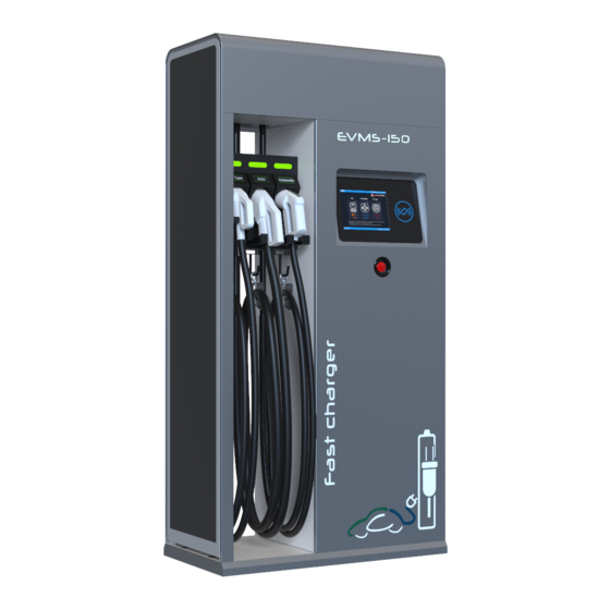
Page 12: Appearance
3.4 Appearance Front View... - Page 13 Internal view Charging status LED charging connector RFID Reader Monitor display Emergency stop button Charging module Industrial Switch leakage protector EVPLC...
-
Page 14: Charger Dust Screen And Air Inlet And Outlet
EVMS-MCM EVMS-MCM2 EVMS-CSU AC input switch 3.5 Charger dust screen and air inlet and outlet Air outlet Air inlet Note: Effective ventilation of equipment In order to prevent dust and obstruct the harmful substances such as PM2.5, the equipment is dust-proofed by adopting international advanced honeycomb textile technology on the side... - Page 15 air filte Note: Please open front door to replace the air filter on the side of the device. There’s butterfly nut at the side of device (no need of any tools), just to pull out the air filter for flushing or fan dust Use a screwdriver to remove 4 screws and open the side door.
- Page 16 To remove the shockproof components at the bottom of the cabinet, you need to open the rear door, left door, and all of them. Use a wrench to remove the bolts at the bottom of the cabinet and remove the wooden base. The installation of the DC charger adopts the method of lower cable entry, the pile body is aligned with the hole, placed on the cement base, fixed with 6 M12*60 anchor bolts, tightened and locked;...
-
Page 17: Charger Diagram
3.6 Charger diagram... -
Page 18: Input Connection Terminals
3.7 Input Connection Terminals A, B, C, Neutral, Grounding input terminal wiring Note: For safety, AC input wiring is recommended to use 150 mm2 cable! The wiring is directly connected to the upper port of the terminal, from left to right: A, B, C. Neutral and Grounding are on the right side of the circuit breaker.Circuit breaker has type A RCD function,RCD rated residual operating current is 30 mA. -
Page 19: Install And Remove The Main Power Module
Install and remove the main power module EV-PLC EVMS-MCM EVMS-CSU Charging module Switch start state After wiring, start the main input switch... -
Page 20: After The Initial Setup Boot
The installation steps of the main power module are as follows: 1. Insert the AC input and DC output of the cabinet into the corresponding module position; 2. Fix the module to the cabinet through the fixing holes on the upper and lower front panel of the module;... -
Page 21: Charger Connector Bin
The charger supports contactless card reader with ISO 14443-compliant Type A, Type B, MF1 cards and ISO7816-compliant PSAM and ESAM cards. (Detail operation with RFID will be provided separately) 3.14 Charging strategy EVMS series electric vehicle charger supports CCS2 charging output modes, The 2 Output Plugs could be used simultaneously. -
Page 22: Charger Parameters
3.15 Charger parameters. Model EVMS-150 Dimension 900*500*2000 Input Rated input voltage 380Vac/400Vac/415Vac Range of inpu tvoltage 304V~456V Input AC limiting voltage 600V Input frequency 50/60Hz; Range:45Hz~65Hz Input PF ≥0.99 Output Interface CCS2 Output voltage 150-1000Vdc Output current 200A max Charging modes Mode 4;... -
Page 23: Part 4 Product Overview
PART 4 Product Overview 4.1 Module Introduction DPM1000/30 charging module is the internal DC power module of out-door integrated DC charging piles, which converts AC to DC and then charge electric vehicles, providing reliable DC supply for equipment requires DC power. The input of charging module is three-phase mains; output DC is adjustable between 150VDC~1000VDC, to meet various voltage demands of different battery packs. - Page 24 number nomenclature Handle DC output & signal pin AC input pin This area has the functions of red, yellow and green indicator lights, among which: 1) The green indicator light indicates normal operation and working status of the charger; 2) The yellow indicator light indicates the alarm state, and it does not light up when the charging module is working normally 3) The red indicator light indicates the fault state, and the charging module does not light up when it is working normally;...
-
Page 25: Feature
4.3 Feature High power density saves system space, 30KW power module; Wide range of input voltage 260V~530V,input surge protection design DSP control, achieves pure digital control from input to output; adopts interlaced series resonance soft switch technology to reduce the tolerance of power devices. ... -
Page 26: Specification
cutting-edge interlaced series resonance soft switch technology to achieve the soft switch of power devices, reduce overall power loss and extend the life of power devices. Digital control Advanced DSP control, achieves pure digital control in protection and management of the whole machine, which can manage the whole machine more accurately and monitor the input, output and internal working status of modules. -
Page 27: Part 6 Charging Operation
PART 6 Charging Operation 6.1Charging Flow Chart The EVMS Series CCS2 lectric vehicle charger operates with a 10.4-inch touch screen with text prompts. Simple operations bring the best experience for users. Below is a flow chart of the charging operation. -
Page 28: Charging Process
6.2 Charging process With pictures to introduce the charging process Manual charge Swipe to charge Charging scan code procedure Start interface Select connector Click the password Scan Charging scan to charge, the default password the QR code and code is "1" enter the password to charge Connect the charger... -
Page 29: Part 7 Enter The Administrator Interface
PART 7 Enter the administrator interface 7.1 How to enter the administrator interface Note:Parameter setup function is limited to maintenance Click the left top corner of below page, come to Maintenance mode password screen, as shown below, the initial password is "888888". -
Page 30: Each Unit Described
7.2 Each unit described Enter the administrator interface: general parameters, charging parameters, background settings, charging verification, alarm threshold, record query, system information, USB wizard, about this machine function... -
Page 31: Part 8 Troubleshooting
PART 8 Troubleshooting Alarm Troubleshooting Background communication Check whether the background system is normal. fault Check whether between output and PE terminal are lack of Insulation fault insulation. Check whether three phase input voltage of input breaker is Input over voltage normal. - Page 32 The product is constantly updating, subject to change without notice. Any person has no right to modify this manual without permission of the manufacturer. The Company reserves the right of final interpretation.
Need help?
Do you have a question about the EVMS Series and is the answer not in the manual?
Questions and answers