Advertisement
Quick Links
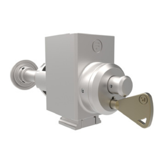
Operating Instructions: S40 IR - Escape Release Adaptor
Description
S40IR Escape Release Adaptor module is used in conjunction with a releasing
amGardS40 unit, to provide an escape function from an interlocked hazardous
area. There are three versions, one with a key reset, one with a push button
reset and one with a simple pull reset. The other option is the length of plunger
needed to clear the door post thickness. This unit must always be mounted as
the first module under the head.
Note: Releasing versions of other modules are the type that MUST be used in
conjunction with this module. This module MUST be mounted directly below the
head module.
Options & Ordering Information
Description
Key Reset
Key Reset
Key Reset
Pull Reset
Pull Reset
Pull Reset
Front Reset (no key)
Front Reset (no key)
Front Reset (no key)
*Suitable for increased post thicknesses up to a maximum of 350mm. For any greater post thickness additional support may be required, contact your
Fortress representative.
Important:
This product is designed for use according to the installation and operating instructions enclosed. It must be installed
by competent and qualified personnel who have read and understood the whole of this document prior to commencing
installation. If the equipment is used in a manner not specified by the manufacturer, the protection provided by the equipment
may be impaired. Any modification to or deviation from these instructions invalidates all warranties. Fortress Interlocks Ltd
accepts no liability whatsoever for any situation arising from misuse or misapplication of this product.
Note: The availability of spare Actuators and Keys makes it possible to easily bypass the safety devices and, for
this reason, the security of any spare Actuators and Keys must be effectively monitored.
DO NOT LEAVE OVERRIDE/RESET KEY IN PLACE!
Always keep it in a secure place, under management control, as it allows access to areas that may have a residual
hazard,and may result in incorrect operation of some devices.
BEWARE OF INTENTIONAL MISUSE CAUSED BY OPERATORS WANTING TO BYPASS SAFETY SYSTEMS. THE
INSTALLER SHOULD ASSESS THE RISKS AND MITIGATE AGAINST THEM.
Safety switches (such as a Stop or LOK) must be fitted in conjunction with this unit to monitor when the Escape
Release has been activated. When lock adaptors are also used it is not possible to change a Stop to a LOK (and
vice versa) without other changes to the locks - seek advice from Fortress.
IF YOU HAVE ANY QUESTIONS OR QUERIES OF ANY NATURE WHATSOEVER PLEASE CONTACT THE SUPPLIER
WHO WILL BE PLEASED TO ADVISE AND ASSIST.
Post Thickness
60mm
80mm
Variable*
60mm
80mm
Variable*
60mm
80mm
Variable*
1
Gard
Part No.
S40R2
S40R3
S40R4
S40R7
S40R8
S40R9
S40RX
S40RY
S40RZ
Advertisement

Summary of Contents for Fortress Technologies am Gard S40
- Page 1 Gard Operating Instructions: S40 IR - Escape Release Adaptor Description S40IR Escape Release Adaptor module is used in conjunction with a releasing amGardS40 unit, to provide an escape function from an interlocked hazardous area. There are three versions, one with a key reset, one with a push button reset and one with a simple pull reset.
- Page 2 Operating Instructions: S40 IR - Escape Release Adaptor amGardS40 IR - Escape Release Adaptor This unit ensures that safe escape can be made through the door, which will activate the safety switch circuits (when fitted to the appropriate host unit) regardless of the locking action of any solenoid or lock being fitted. •...
- Page 3 Operating Instructions: S40 IR - Escape Release Adaptor Figure 2: Dimensional Drawing - 2 OFF M8 X 15 (ACCESS FROM THE REAR) Figure 3: Dimensional Drawing - S40R4 ONLY S40R4, S40RZ ONLY 83 MAX PANEL THICKNESS (338 REF.) (SHOWN IN UN-TRIGGERED STATE) M8 THREADED ROD TO BE FIXED AT BOTH ENDS WITH LOCTITE 243 THREADLOCKER OR EQUIVALENT...
- Page 4 Operating Instructions: S40 IR - Escape Release Adaptor Figure 4: Dimensional Drawing - PANEL MOUNTING FOR S40R2, S40R3, S40R7, PANEL CUTOUT DETAIL A. S40R8, S40RX & S40RY TYPES REQUIRED FOR ALL S40 IR ESCAPE RELEASE ADAPTORS. 8.5 CLEARANCE HOLES TO SUIT M8 REAR FIXING 36.
-
Page 5: Service And Inspection
Operating Instructions: S40 IR - Escape Release Adaptor Mounting 1. Locate the device so that inspection and replacement are possible. 2. Mount the enclosure assembly together with head assembly to a flat metal, static part of the machine. Use M8 screws from the rear. - Page 6 Operating Instructions: S40 IR - Escape Release Adaptor Disposal The S40 IR Adaptor does not contain any certified hazardous materials so should be disposed of as industrial waste. Liability Coverage is Voided Under the Following Conditions: • If these instructions are not followed •...
Need help?
Do you have a question about the am Gard S40 and is the answer not in the manual?
Questions and answers