Table of Contents
Advertisement
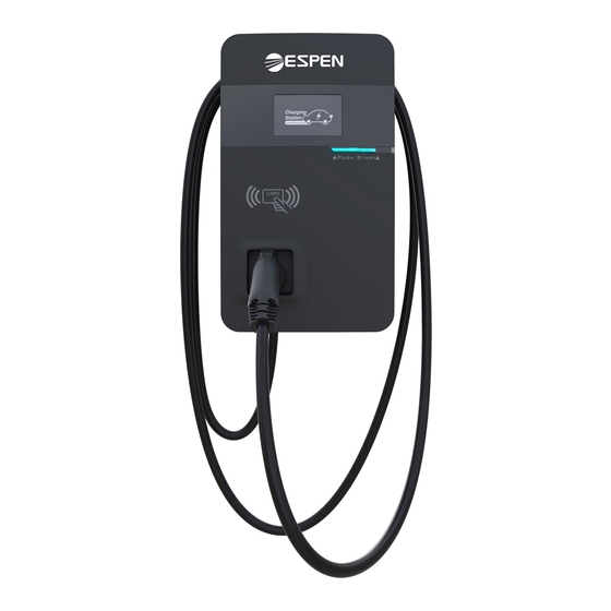
Electric Vehicle AC Charger
Applicable to:
Espen Level 2 Standard+ 48A Chargers
Model: EVC/A48 series
Espen Level 2 Fleet 80A Chargers
Model: EVC/A80 Series
High-End Edition
NEMA 4R Authorization
COPYRIGHT © 2021 reserves the right to make changes to this product without further notice.
User Manual
Push Start
Management
Push Start
Classic Edition
Repairable
Outdoors
Advertisement
Table of Contents

Summary of Contents for ESPEN EVC/A48 Series
- Page 1 Electric Vehicle AC Charger User Manual Applicable to: Espen Level 2 Standard+ 48A Chargers Model: EVC/A48 series Espen Level 2 Fleet 80A Chargers Model: EVC/A80 Series Push Start Push Start High-End Edition Classic Edition NEMA 4R Authorization Management Repairable Outdoors...
-
Page 3: Table Of Contents
CONTENT 1. Important Safety Instructions ..............1 2. Federal Communication Commission Interference Statement ... 3 3. Industry Canada statement ..............5 Interface..................... 7 4.1 High-End Edition ................. 7 4.2 Classic Edition ..................8 ..............9 4.3 Bottom Case and Wire box 5. -
Page 4: Important Safety Instructions
Standard+ 48A Series - User Manual 1. Important Safety Instructions Please read all Important Safety Instructions as well as charging instructions in your vehicle owner’s manual before attempting to charge your electric vehicle. Failure to do so can result in death or severe injury. Save this user manual for future reference. - Page 5 Green Power, Green Lifestyle. • Risk of explosion. This device has arcing or sparking parts that should not be exposed to flammable vapors. • Risk of electric shock. Do not remove the cover or attempt to open the enclosure of this device. There are no user-serviceable parts inside. Contact a qualified service company if you require any service repairs.
-
Page 6: Federal Communication Commission Interference Statement
Standard+ 48A Series - User Manual 2. Federal Communication Commission Interference Statement This device complies with Part 15 of the FCC Rules. Operation is subject to the following two conditions: (1) This device may not cause harmful interference, and (2) this device must accept any interference received, including interference that may cause undesired operation. - Page 7 Green Power, Green Lifestyle. This transmitter must not be co-located or operating in conjunction with any other antenna or transmitter. Radiation Exposure Statement: This equipment complies with FCC radiation exposure limits set forth for an uncontrolled environment. This equipment should be installed and operated with minimum distance 20cm between the radiator &...
-
Page 8: Industry Canada Statement
Standard+ 48A Series - User Manual 3. Industry Canada statement: This device complies with ISED’s licence-exempt RSSs. Operation is subject to the following two conditions: (1) This device may not cause harmful interference, and (2) this device must accept any interference received, including interference that may cause undesired operation. - Page 9 Green Power, Green Lifestyle. l'antenne et les utilisateurs, et 2) Le module émetteur peut ne pas être coïmplanté avec un autre émetteur ou antenne. Ta n t q u e l e s 2 c o n d i t i o n s c i - d e s s u s s o n t re m p l i e s , d e s e s s a i s supplémentaires sur l'émetteur ne seront pas nécessaires.
-
Page 10: Interface
Standard+ 48A Series - User Manual 4. Interface 4.1 High-End Edition 5” LCD Screen LED Light Indication Push Start SAE J1772 AC Charging Connector Wall-Mount Bracket with Power Box AC Power Inlet Charging Cable Inlet... -
Page 11: Classic Edition
Green Power, Green Lifestyle. 4.2 Classic Edition LED Light Indication Push Start SAE J1772 AC Charging Connector Wall-Mount Bracket with Power Box AC Power Inlet Charging Cable Inlet... -
Page 12: Bottom Case And Wire Box
Standard+ 48A Series - User Manual 4.3 Bottom Case and Wire box Blade Male connector Power and Grounding Setting For 4G SIM Card Network and setting Port Ethernet Inlet AC Inlet Blade Female Connector AC Inlet Hole Ethernet Inlet Hole... -
Page 13: Dimensions (Unit:mm)
Green Power, Green Lifestyle. 5. Dimensions (unit:mm) 5.1 Main Size of Charger Push Start 5.2 Wall-Mount Bracket 264.7 369.7 337.8 257.8 197.8 163.8... -
Page 14: Specification
Standard+ 48A Series - User Manual 6. Specification 200-240 VAC / Single Phase Rated Input Voltage Rated Output Current AC Power Frequency 50/60 Hz UVP, OVP, Surge protection, Ground fault Input Protection OCP, Control pilot fault, Residual current protection Output Protection SAE J1772 AC Charging Connector Output Interface Storage Temperature... -
Page 15: Status Description Of The Charger Indication Lights
Green Power, Green Lifestyle. 7. Status Description of the Charger Indication Lights Work status Blue Green Constantly Bright Initial (White) Idle Backend Breath connected Sleep Idle Constantly Backend connected Bright Idle Backend Breathing disconnected Sleep (Yellow) Idle Constantly Bright Backend disconnected (Yellow) Authorize RFID Flicker... -
Page 16: Screen Instructions
Standard+ 48A Series - User Manual 8. Screen Instructions 8.1 Status bar Status Code Ethernet connected Ethernet Not Con- with internet nected Ethernet connected without internet WiFi connected WiFi Not Connected with internet WiFi connected without internet 4 G c o n n e c t e d 4G Not Connected with internet 4 G c o n n e c t e d... - Page 17 Green Power, Green Lifestyle. 012241 WiFi module communication fail 012242 3G/4G module communication fail 012243 RFID module communication fail 012254 Fail to create share memory 012255 CSU initialization failed 012256 Ground Fault 012257 MCU self-test Fault 012262 Syetem output Circuit Short 012344 Meter IC communication timeout 012345...
-
Page 18: Installation Instructions
Standard+ 48A Series - User Manual 9. Installation Instructions 9.1 Safety Requirements • Read this user manual thoroughly and make sure to review all local building and electrical codes before installing the AC charger. A qualified technician should install the AC charger according to the user manual and local safety regulations. -
Page 19: Power Grid Connection And Grounding Type
Green Power, Green Lifestyle. 9.2 Power Grid Connection and Grounding Type • This AC charger supports different power grid connections and grounding types. You can configure through the setting dip switch. Setting methods are shown below. • Before setting the dip switch, make sure the input power is turned OFF. - Page 20 Standard+ 48A Series - User Manual Maximum Output Current This AC charger can support different maximum output current through the setting rotary switch. Setting methods are shown below • Before setting the rotary switch, make sure the input power is turned OFF. •...
-
Page 21: Packing List
IP55 Authorization Management Repairable Outdoors version. W84A99900086-HB5 COPYRIGHT © 2020 Espen Technology reserves the right to make changes to this product without further notice. Product Name Quantity Note AC Charger (With Charging Cable) Wall-Mount Bracket & Inlet Box User Manual... -
Page 22: Tools And Materials Required
Standard+ 48A Series - User Manual 9.4 Tools and Materials Required Tools required before installing the charger onto the Wall-Mount Bracket are: • Wire stripper • Crimpers for ring terminals • Phillips screwdriver for M4 – M6 1-3/8 inch or 34 mm drill bit •... -
Page 23: Installation Requirements
Green Power, Green Lifestyle. 9.6 Installation Requirements • To select the best location and position to install the wall-mount unit, you should first determine the parking position of the vehicle to ensure the charging connector can be easily inserted into the vehicle charging inlet. - Page 24 Standard+ 48A Series - User Manual STEP 1 Installation of the wall-mounted metal plate Take out the wall-mounted metal plate and locate all the installation holes. Use as a template to mark on the wall with a pencil or any tool, and insert 4 sets of expansion bolts (M5X40mm) into the wall, as shown in the figure.
- Page 25 Green Power, Green Lifestyle. STEP 2 Installation of the wire box First, remove the waterproof cover at the inlet end marked as "AC In". Then, install the accessory "1-inch liquidtight flexible metal conduit" at the inlet of the power cord, and attach the wire box to the wall-mounted metal plate with screws.
- Page 26 Standard+ 48A Series - User Manual STEP 4 Installation and setting of the network cable Remove the waterproof plug from the Internet interface at the bottom left of the wire box. Feed the network cable into the wire box through the network cable entrance.
- Page 27 Green Power, Green Lifestyle. STEP 6 Installation of the SIM card (only available for 4G models) Attention: Please confirm that the SIM card password has been removed prior to installation, as the charger post does not support SIM cards with passwords.
- Page 28 Standard+ 48A Series - User Manual Next, move the charger equipment in a horizontal direction, so that the AC connector of the equipment can be inserted into the conductive spring plate of the wire box. Meanwhile, apply pressure to the equipment, so that the three screw holes of the equipment align with the three holes of the wall-mounted metal plate.
- Page 29 Green Power, Green Lifestyle. STEP 8 Power on the machine for setting of the charger For setting instructions, please refer to Section 10.1–10.4 "Charger Standard Setting instructions" Push Start Electric box STEP 9 Power off and unplug the connection Power off the machine and remove the network cable once setting is completed (For those who are in a wired network environment, please go straight to Step 10) Push Start...
- Page 30 Standard+ 48A Series - User Manual Remove the three screws on the charger in the order bottom - right - left. Pull the network cable out of the wire box , then remove the network cable. Install the waterproof plug, then re-install the charger and wire box.
- Page 31 Green Power, Green Lifestyle. Let the three screw holes of the equipment align with the three holes of the wall-mounted metal plate, then tighten with the M6 plum screws in the order left - right - bottom, with a tightening torque of 30 kg-cm.
- Page 32 Standard+ 48A Series - User Manual STEP 10 Installation of charging gun wiring Wrap the charging gun wire around the equipment (about two turns), so that the charging gun wire will not hang down to the ground. Once the wrapping is done, insert the charging gun head into the hole of the charging gun base on the front panel of the machine to complete the installation of the equipment.
-
Page 33: Charger Standard Setting
Green Power, Green Lifestyle. 10. Charger Standard Setting 10.1 Time setting Automatic setting : The time will be adjusted automatically when the charger connects to the internet. Time Server : • time.windows.com • cn.ntp.org.cn • tock.stdtime.gov.tw Note: The firewall and network environment may influence the time server connection. - Page 34 Standard+ 48A Series - User Manual STEP3/ Open a browser and enter IP address 192.168.1.10 192.168.1.10 to log into the setup page. Use login https://192.168.1.10 the following credentials to log in. Account admin • Account: admin Password 1231231238 • Password: 1231231238 STEP4/ Select "SET"...
-
Page 35: Wi-Fi Setup
Green Power, Green Lifestyle. 10.2 Wi-Fi Setup Tools required before setting • Notebook with RJ45 interface x 1 • One RJ45 cable connector is male to male x1 Wi-Fi Setting STEP1/ Select "SET" at the top of the webpage 192.168.1.10 to enter the settings page. -
Page 36: Setup (For The Optional 4G Edition)
AX Series - User Manual Standard+ 48A Series - User Manual 10.3 4G Setup (for the optional 4G Edition) Attention: Please confirm that the SIM card password has been removed prior to installation, as the charger post does not support SIM cards with passwords�... -
Page 37: Re-Checking The Wi-Fi And 4G Signal Strength On Power-Up
Green Power, Green Lifestyle. Green Power, Green Lifestyle. 10.4 Re-checking the Wi-Fi and 4G Signal Strength on Power-Up. After restarting the charger, check the connection signal strength. The RSSI (Received Signal Strength Indication) should be higher than -65dBm. If the value is lower, you may experience a weak Wi-Fi signal connection or even disconnection. - Page 38 Standard+ 48A Series - User Manual STEP5/ Select the Wi-Fi and 3G/4G module to 192.168.1.10 enter the setting. Network Network Status Ethernet WiFi 3G/4G STEP6/ (Wi-Fi Version) 192.168.1.10 Network • Make sure the Wi-Fi strength is higher than Wi-Fi -65dbm. Mode SSID RSSI...
-
Page 39: Local Load Balance Mode (Offline Only)
Green Power, Green Lifestyle. Green Power, Green Lifestyle. 11. Local Load Balance Mode (OFFLINE only) • When selecting Local Load Balance Mode,there must be a minimum of 2 and a maximum of 4 chargers of the same model, and no more than 5 including the master. - Page 40 Standard+ 48A Series - User Manual Usage example: LAN containing three devices Maximum output of devices: 48A Number of devices: 3. Example 1: If there is only one charging device in use in the charging LAN, the master will authorize maximum current output to the device in use, including if only the master is in use.
-
Page 41: Operating Procedure
Green Power, Green Lifestyle. 11.1 Operating procedure STEP 1 Select master If the charger still has the default factory settings, it can be used as the master without need for setup, but if other settings have already been completed on the charger, please first refer to Master Setup below. Master Push Start Push Start... - Page 42 Standard+ 48A Series - User Manual STEP 2 Master Setup • The rotary switch needs to be set to the default value B NOTE! If the local mains power system does not support 48A, please adjust according to the size of the local power load. The master will output current according to the set power level.
- Page 43 Green Power, Green Lifestyle. STEP 3 Master Webpage Wi-Fi Setup STEP1/Open a browser and enter the IP 192.168.1.10 address 192.168.1.10 to log into the setup login https://192.168.1.10 page. Use the following credentials to log in. Account admin • Account: admin Password 1231231238 •...
- Page 44 Standard+ 48A Series - User Manual S T E P 5 / S e l e c t " S E T " a t t h e t o p o f t h e 192.168.1.10 webpage to enter the settings page. Select "Backend"...
- Page 45 Green Power, Green Lifestyle. STEP 4 Confirm Model Name and Serial Number of Master Check the model name and S/N information on the model label located on the side of the device. When setting up connection on slave devices, the master device information will be used as the account password.
- Page 46 Standard+ 48A Series - User Manual STEP 5 Select Slave • Make sure that the number of slaves does not exceed 4 • There must be no walls or obstructions that affect communication between master and slaves • It is recommended that the master be located in the middle of all the slaves, to ensure the best signal reception Master Push Start...
- Page 47 Green Power, Green Lifestyle. STEP 6 Set Rotary Switch on Slave Turn the charger around so that the rear side is facing you. Find the rotary switch and rotate it to the F position. Rotary switch...
- Page 48 Standard+ 48A Series - User Manual STEP 7 Set Slaves to Connect to Master This setup procedure connects the slaves to the master to form a local area network (LAN). STEP1/Open a browser and enter the IP 192.168.1.10 address 192.168.1.10 to log into the setup login https://192.168.1.10 page.
- Page 49 Green Power, Green Lifestyle. S T E P 5 / S e l e c t " S E T " a t t h e t o p o f t h e 192.168.1.10 webpage to enter the settings page. Select "Backend"...
- Page 50 Standard+ 48A Series - User Manual STEP 8 Check Master and Slave Connection Status 192.168.1.10 Make sure that the Wi-Fi strength is higher Network than -65dBm. Wi-Fi Mode SSID Password RSSI -65dbm DHCP Client STEP 9 Setup Complete Master Push Start Push Start Push Start Push Start...
-
Page 51: Operating Instructions
Green Power, Green Lifestyle. 12. Operating Instructions Standby - Green Light Wait to see the standby light show STEADY GREEN. When the charger is not operated for Push Start 120 seconds, it will enter sleep mode. When the machine is a connected to the backend, the standby light remains GREEN, and it becomes SLEEP GREEN when the machine enters sleep mode. - Page 52 Standard+ 48A Series - User Manual Waiting for Charging - Blue Light After the vehicle connector is connected to the vehicle inlet, the CHARGE light is constantly lit. Charging - Blue Light Flashing The CHARGE light flashes while charging. Push Start Fault - Red Light The red light is lit when a fault occurs.
-
Page 53: Error And Warning Message
Green Power, Green Lifestyle. 12.1 Error and Warning Message Status Remark One flash followed Please measure the input voltage to see if it Input OVP by a 3-sec pause is higher than 275V T w o f l a s h e s Please measure the input voltage to see if it Input UVP followed by a 3-sec... - Page 54 Standard+ 48A Series - User Manual *1 Verify that the Wall Connector is properly grounded. The ground connection must be bonded in the upstream power supply for proper operation. Check all physical connections, including the wire box terminals, electrical panel(s), and wire box. In residential power supplies, check the bond between ground and neutral at the main panel.
-
Page 55: Maintenance And Repair
Green Power, Green Lifestyle. 13. Maintenance and Repair 13.1 Daily Maintenance Please keep the charger clean and install it in a clean area with low humidity. Do not install it in an environment near the sea, with high levels of oil, humidity or dust. •... -
Page 56: Warranty And Maintenance
Standard+ 48A Series - User Manual 13.3 Warranty and Maintenance • The warranty period for this charger is two years and covers parts only. • All replacement parts provided during the warranty period will be covered for the remaining balance of the original warranty period, in addition to a 90-day grace period. -
Page 57: History
Green Power, Green Lifestyle. 13.4 Maintenance History Product Name Serial No. Product Model Manufacture Date Year Month Customer Phone Address 1.Maintenance Content Signature of Customer After Service 2.Maintenance Content Signature of Customer After Service 3.Maintenance Content Signature of Customer After Service 4.Maintenance Content Signature of Customer After Service... - Page 58 NOTE...
- Page 59 NOTE...
- Page 60 Manufacturer Contact Info Sticker...
Need help?
Do you have a question about the EVC/A48 Series and is the answer not in the manual?
Questions and answers