Advertisement
Quick Links
Advertisement

Summary of Contents for EZ Power Steering EZ ELECTRIC POWER STEERING
- Page 1 EZ ELECTRIC POWER STEERING INSTALLATION MANUAL Austin Healy MKIII...
- Page 2 CONTENTS 1. THE PRODUCT _______________________________________________ 2. OVERVIEW OF THE KIT ________________________________________ 3. INSTALLATION _______________________________________________...
- Page 3 If you do not have the skills or tools to carry out the installation, then have a professional fit the kit for you. EZ Power Steering cannot be held accountable for a faulty installation or damages to the kit or vehicle.
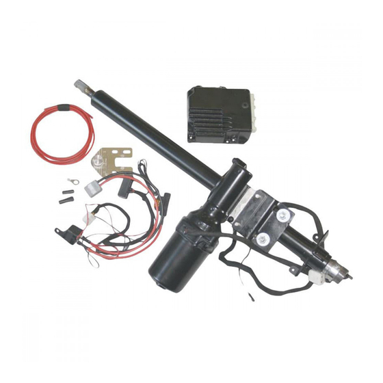
- Page 4 OVERVIEW OF THE KIT EZ-AH3-1. Complete Set EZ-AH3-2. Wiring loom with potientiometer EZ-AH3-3. 6mm electric cable EZ-AH3-4. Input side EZ-AH3-5. Output side EZ-AH3-6. Clamp EZ-AH3-7. ECU...
- Page 5 INSTALLATION Step 1. Check tire pressure, take the car for a test drive and check the steering system for defects and alignment. If everything is working correctly, continue with the conversion. Step 2. Locate an ignition switched plus wire and label it. Disconnect the earth cable from battery (also check if the car has a positive or negative earth).
- Page 6 Step 4. Remove both dash gauges to improve accessibility. Step 5. Measure the distance from the steering shaft to the dash. Make a note of this.
- Page 7 Step 6. Remove the upper mounting bracket from the original steering column Step 7. Remove the cover to get access to the lower mounting points from the steering column.
- Page 8 Step 8. Remove the lower mounting bolts from the original column (via the removed cover). The bracket needs to be cut, so that it can be removed completely. (see photo for cutting line). Step 9. Cut the steering tube as low as possible.
- Page 9 Step 10. Cut the steering shaft at the right length. Measure the length from the power steering columns, including the output shaft. This length can be cut off from the original shaft. (Caution: do not measure the length from the piece which goes into the steering shaft).
- Page 10 Step 12. Fit the output shaft in the original steering shaft. Weld it to the original shaft. CAUTION: the EZ output shaft is ready to fit the original steering shaft. Once the original steering shaft has been replaced, it's possible that the EZ output shaft doesn't fit.
- Page 11 Step 14. Slide the mounting clamp over the steering tube. Step 15. Install the mounting bracket behind the gauges.
- Page 12 Step 16. Connect the EZ power steering harness to the car. Check if the car is positive or negative earth. Step 17a. NEGATIVE EARTH: Connect the thick red wire (30+) through the fuse holder direct to the battery plus. Fahrgestell.
- Page 13 Step 18b. Connect the thin red wire at the same point as the 30+ wire. Connect the white wire to the ignition switched earth. (see attachments at last page). Step 19b. Connect the black wire, through the fuse holder directly with the battery negative Step 20.
- Page 14 Step 21. Slide the output flange over the original tube. Slide the clamp over the output shaft afterwards. Step 22. Install the EZ unit onto the output flange. Tighten all 3 mounting bolts. The clamp from the output shaft can be fastened through the opening into the output flange.
- Page 15 Step 23. Position the EZ unit into the right position (also see point 5) and tighten the lower clamp through the heater channel (see point 14). Step 24. Install the upper clamp and tighten it.
- Page 16 Step 25. Cut off the tube from the indicator switch (be careful not to damage the internal wiring). For the best result it is best to use a pipe cutter. Step 26. Weld the inner ring to the outer ring. Use 3 spot-welds to do this.
- Page 17 Step 27. Use a multimeter to determine which wires correspond (wires through the steering shaft and contact pins) Install steering wheel and indicator switch to the EZ unit. Connect the original wiring from the indicator switch to the contact pins at the EZ unit. Step 28.
- Page 18 Step 30. Take a test drive and recheck that all systems are functioning correctly. Step 31. The end result. (Picture is an example of an Austin Healey with a collapsible column.)
- Page 19 Positive Earth Attachment. When you have a positive earth car, the EZ Powersteering wire harness has a extra relay which switches the 15+. See the schematic below. Keep in mind, that at a positive earth car, the battery + is connected to the chassis. The Thick red wire (30+) needs to be connected to the chassis.
Need help?
Do you have a question about the EZ ELECTRIC POWER STEERING and is the answer not in the manual?
Questions and answers