Table of Contents
Advertisement
Quick Links
DU35K/FDM/ND
Frequency Deviation Display with Ethernet Interface
Instruction Manual
Sipronika d. o. o., Verovškova 64a, 1000 Ljubljana, Slovenija, Tel.: 01/ 421-52-50
E-mail: info@sipronika.si, Internet: http://www.sipronika.si
Ljubljana, 17. 06. 2021, Copyright Sipronika 2018-21, All rights reserved.
DU35K-FDM_2.1.eng.doc
Advertisement
Table of Contents

Summary of Contents for Sipronika DU35K
- Page 1 DU35K/FDM/ND Frequency Deviation Display with Ethernet Interface Instruction Manual Sipronika d. o. o., Verovškova 64a, 1000 Ljubljana, Slovenija, Tel.: 01/ 421-52-50 E-mail: info@sipronika.si, Internet: http://www.sipronika.si Ljubljana, 17. 06. 2021, Copyright Sipronika 2018-21, All rights reserved. DU35K-FDM_2.1.eng.doc...
- Page 2 Sipronika d.o.o. Verovškova 64a 1000 Ljubljana Tel.: 01/4215-250 Internet: http://www.sipronika.si E-mail: info@sipronika.si June 2021 DU35K-FDM_2.1.eng.doc DU35K/FDM – Instruction Manual Page 2...
-
Page 3: Table Of Contents
CONTENTS IMPORTANT SAFETY INSTRUCTIONS ............ 4 INTRODUCTION ..................5 MOUNTING AND CONNECTION OF DU35K/FDM ........6 Mounting ............................6 Connection and display’s operation ................... 7 SETTINGS, THE USE OF THE PUSH-BUTTONS “MENU” AND “SET” .. 8 Menu description .......................... 8 SETTINGS THROUGH THE NETWORK .......... -
Page 4: Important Safety Instructions
Electrical Hazard – Failure to follow the instructions may result in electric shock and injury to persons. Danger – risk of damage to equipment if the instructions are not followed. Sipronika d.o.o. disclaims all responsibility in case of accident or damage caused by an improper use of the product. DU35K/FDM – Instruction Manual... -
Page 5: Introduction
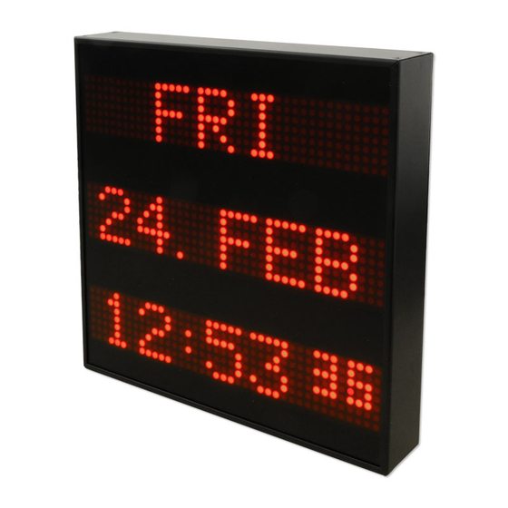
2. INTRODUCTION The DU35K/FDM/ND digital display is designed for displaying frequency and its deviation in 50/60 Hz power line networks. It can work only in connection with a device, which can measure and provide frequency deviation data – e.g. Lantime server with built-in FDM511 module. -
Page 6: Mounting And Connection Of Du35K/Fdm
3. MOUNTING AND CONNECTION OF DU35K/FDM 3.1 Mounting Standard version of DU35K/FDM/ND is intended for wall mounting. For this purpose two wall screws on which the clock will be hung, need to be installed. Mounting carrier on the rear panel can be fixed in different positions –... -
Page 7: Connection And Display's Operation
The display receives FDM strings from the Lantime server. In order to work with the DU35K/FDM/ND it should be configured properly. You can find more details in the documentation of the Lantime, e.g. https://www.meinberg.de/download/docs/manuals/english/ltos_6-24.pdf, page 136, chapter FDM Configuration “New Receiver”. -
Page 8: Settings, The Use Of The Push-Buttons "Menu" And "Set
1 (the lowest brightness) to 3 (the highest brightness). SERIAL NUMBER If you press the SET key, the display's serial number is displayed. The number is written also at the display's rear; it can not be altered. DU35K/FDM – Instruction Manual Page 8... - Page 9 If you press the SET key, the display returns to the normal displaying of time and messages. If there were changes in settings, you’ll have to confirm that you really want to apply them. However, if you press the MENU key, the display begins a new circle of settings. DU35K/FDM – Instruction Manual Page 9...
-
Page 10: Settings Through The Network
With Message Editor it is possible also to perform display’s firmware updates. 5.2 Installation You can download Message Editor from https://sipronika.si/downloads/. Run medxxxx_setup.exe" setup program. Xxxx is usually replaced by version number. In the installation program, choose the language and the folder in which you want to install the program, as well as the program group into which the icons will be installed. - Page 11 If you click on the devices name on the list of devices, on the right side of its name, its serial number and IP address show up. The name is by default the same to the device’s serial number, DU35K/FDM – Instruction Manual Page 11...
- Page 12 Settings« the display network settings are listed. If needed, you can also change them. All current settings can be retrieved by clicking on »Refresh settings«. The fields NTP1, NTP2, NTP3 and Stratum are not relevant in case of the DU35K/FDM/ND. By clicking on »Send settings« the settings are sent to the display.
-
Page 13: Connectors Description
6. CONNECTORS DESCRIPTION PC IN Fig. 4: Connector pin assignment. At the DU35K/FDM/ND they are used only for servicing purposes. Apart from the network connector RJ-45 and IEC inlet for the mains connection there are two additional D-SUB connectors on the rear panel. One of them is labelled with “OUT” and the other with “PC IN”. -
Page 14: Technical Specifications
20 W Fuse: Internal, built in power supply 320 mm 320 mm 54 mm (not including the mounting carriers) Dimensions: Weight: 3.9 kg Protection class: IP30 0..50° C Temperature range: DU35K/FDM – Instruction Manual Page 14...
Need help?
Do you have a question about the DU35K and is the answer not in the manual?
Questions and answers