Table of Contents
Advertisement
Quick Links
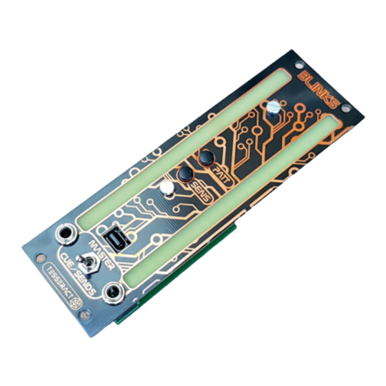
BLINKS is an 8HP Eurorack VU meter with 24 RGB leds per channel. It's very simple
to use: it has 2 inputs, one for each led column, and 2 buttons with multiple functions. The
easy way explanation of the functions:
PATT
PATT long press
SENS
SENS long press
The module has a built-in 5V regulator, in case you don't have 5V in your Eurorack
PSU. You can use JP1 jumper on the back side to select between the led board powered
from the 5v rail or by the internal regulator (which is powered from the +12v rail).
30 mA ( on lowest brightness), 5 v rail not necessary for operation
+5v:
4mA ( or ~40mA if 5 v rail is not used)
+12v:
-12v:
4mA
Up to 3 stereo signals can be connected to the
Easy
D IY
with only a few components, the led board is already assembled.
BLINKS
->
change pattern
->
change color scheme
->
adjust sensitivity
->
adjust brightness
b uffered input
using the rear headers.
Advertisement
Table of Contents

Summary of Contents for Tesseract Modular BLINKS
- Page 1 BLINKS BLINKS is an 8HP Eurorack VU meter with 24 RGB leds per channel. It's very simple to use: it has 2 inputs, one for each led column, and 2 buttons with multiple functions. The easy way explanation of the functions: PATT ->...
- Page 2 PATT button changes the led pattern ( 6 patterns to choose ). SENS button changes the audio input sensitivity, cycling in 7 steps. Color Scheme selection: Long press PATT b utton to enter the c olor scheme selection for the current pattern. Use both buttons to navigate through different color schemes, long press PATT again to save the settings.
- Page 3 happens after the buffer, which protects the integrity of the signals connected to those headers. Both JP2 and JP3 have the same pin assignment: The toggle switch selects the signal to be displayed (unless, as we said, there’s something plugged in the front mini jacks). Signals plugged in the MASTER pins go directly to the toggle switch, signals plugged in CUE and SEND pins go to JP4, there, 2 jumpers selects which one will be directed to the toggle switch.
- Page 4 Other Solutions are possible without soldering, using f emale jumper wire , for example, taking the signal from those pins of Master Section’s JP5 will monitor the same mix you have in headphones, but unaffected by the phone level pot neither the master volume pot.
- Page 5 “click” fine, if not, go back place another pair of washers behind the panel to make enough room. Finally, place the Blinks pcb. Screw the mini jack & toggle switch nuts and the M3 nut to secure the Blinks pcb.
Need help?
Do you have a question about the BLINKS and is the answer not in the manual?
Questions and answers