Pioneer SX-950 Procedure
Alignment procedures
Hide thumbs
Also See for SX-950:
- Manual (73 pages) ,
- Operating instructions manual (21 pages) ,
- Operating instructions manual (21 pages)
Advertisement
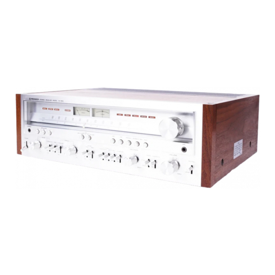
SX-950
9.1 AM SECTION
1. Set function switch to AM.
2. Connect AM signal generator through 1k-ohm
resistor to AM antenna terminal.
3. Set DUPLICATE switch to OFF and connect
an AC voltmeter to TAPE 1 REC jacks.
4. Set AM SG for 400Hz 30% modulation 100dB
output.
5. Set SX-950 dial indication and AM SG
frequency for 600kHz.
6. Adjust
T8
core for maximum reading on AC
voltmeter.
7. Set SX-950 dial indication and AM SG
frequency for 1,400kHz.
A
LIGNMENT
8. Adjust
9. Set AM SG for 30dB output.
10. Set SX-950 dial indication and AM SG
11. Adjust T7,
12. Set SX-950 dial indication and AM SG
13. Adjust TC5,
14. Repeat steps 10-13 to eliminate variations in
P
ROCEDURES
TC5
for maximum reading on AC
voltmeter.
frequency for 600kHz.
T8
and
bar antenna core
maximum reading on AC voltmeter.
frequency for 1,400kHz.
TC6
and
reading on AC voltmeter.
AC voltmeter readings.
for
TC7
for maximum
Advertisement
Table of Contents

Related Manuals for Pioneer SX-950


Summary of Contents for Pioneer SX-950
- Page 1 AM antenna terminal. 9. Set AM SG for 30dB output. 3. Set DUPLICATE switch to OFF and connect 10. Set SX-950 dial indication and AM SG an AC voltmeter to TAPE 1 REC jacks. frequency for 600kHz. 4. Set AM SG for 400Hz 30% modulation 100dB 11.
- Page 2 5. Set FM SG for 100dB output at 400Hz and horizontal input terminal of oscilloscope. 100% modulation. 28. Through probe, connect oscilloscope vertical 6. Set SX-950 dial indication and FM SG input terminal to terminal No. 19. frequency for 87.4MHz. 29. Set FM SG for 98MHz 60dB output 7.
- Page 3 Local Oscillator back to where it belongs with a bit of luck and careful adjustment. Set the SX-950 tuning pointer to about 98 MHz, at the indicated frequency of a known station very close to 98. Then get another FM receiver tuned to this station to hear the audio content. Verify that the movable fins of the SX-950 tuning variable capacitor are at their approximate midpoint as well.
- Page 4 9.3 POWER AMPLIFIER SECTION 1. Turn VR3 and VR4 fully counter-clockwise before turning on the power. 2. Remove jumper plugs connecting POWER IN and PRE OUT jacks. 3. Connect 5.1 K-ohm resistor to POWER IN jacks. 4. Set power amplifier for no load. 5.
Need help?
Do you have a question about the SX-950 and is the answer not in the manual?
Questions and answers