Table of Contents
Advertisement
Quick Links
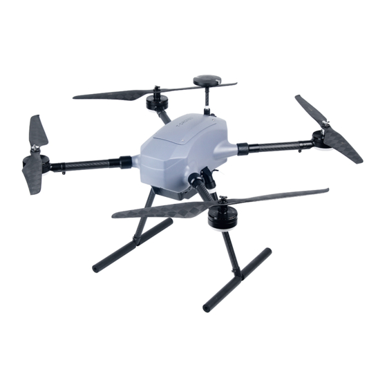
M690PRO
Long Flight Time Flight platform
01 MAIN FEATURES
Being a platform of ultra-light, long endurance and multiple applications, this aircraft can be employed for various missions
with corresponding equipment including aerial photography, mapping and surveying,meteorological monitoring, surveillance,
military supervision and geoexploration etc. Custom solutions are also available.
The endurance of M690PRO reaches up to 55mins (1kg payload). The abundant flight time enables more mission
accomplishment in one flight. It can be adapted to a variety of devices with flexible and diverse mounting methods.It is easy
for the M690PRO to shuttle in different environments with long communication distance, excellent protection capability and
a portable backpack.
02 FEATURES
Ultra-light materials and structural optimization to obtain longer flight time.
The low center of gravity design makes the aircraft more reliable.
Enhanced protection level;Ease of use.
The arms, landing gears and propellers can be folded and disassembled quickly.
Chute design for easy installation of battery.
No tools required. Only 3 minutes to get ready to fly.
03 SPECIFICATIONS
Wheelbase
700mm
Weight
3.69kg
(no payload)
AUW
6kg
Max.descending Speed
3m/s
Vertical ±0.2m;
Hover Precision
Horizontal ±0.1m
(Without RTK)
IP54
Protection Level
﹣15℃~50℃
Working Environment
Control System
PIXHAWK
283*278*175mm
Folded Size
(incl. Landing gears; excl. props)
6.6kg
Package Weight
UNBOXING WARNING
For the safety and steady operation of drones during assembly and calibration, please make sure all parameters are at the
proper values before takeoff.
Frame Weight
1.69kg
(incl. Propulsion system & FC)
2.23kg
,
(Smart battery)
Battery Weight
1.95kg
(Li-ion battery)
Max. Ascending Speed
5m/s
Max.cruising Speed
15m/s
1kg payload≥55mins;
Hover Time
2kg payload≥40mins
Wind Resistance Level
14m/s
Propulsion System
T-MOTOR
Unfolded Size
550*550*445mm
(Excl. Props)
420*370*280mm
(standard)
Packing
510*420*340mm
(Backpack)
2
;
Advertisement
Table of Contents

Summary of Contents for T-Motor T-DRONES M690PRO
- Page 1 1kg payload≥55mins; Hover Time Hover Precision Horizontal ±0.1m 2kg payload≥40mins (Without RTK) IP54 Wind Resistance Level 14m/s Protection Level ﹣15℃~50℃ Propulsion System T-MOTOR Working Environment Control System PIXHAWK Unfolded Size 550*550*445mm (Excl. Props) 420*370*280mm ; (standard) 283*278*175mm Folded Size Packing 510*420*340mm (incl.
- Page 2 INSPECTIONS BEFORE TAKEOFF AFTER LANDING Please carry out proper debugging and checks on every part of the drone Any minor neglect may result in severe damages 1.After landing, ensure that the remote control is locked, and then cut off the power supply of the UAV. or accidents.
- Page 3 3. Spread the arms to 180 degrees and turn the folding rings as per the instruction and secure the arms.(Make sure the 05 ASSEMBLY arms are lined up with the frame, otherwise, they might get stuck and cause damage to the thread. ) (Figure 3) 1.
- Page 4 5. Attach the landings gears to the frame as per Figure 5. Assembly completes as shown Figure 6. (Please be aware of the 06 FC INSTALLATION (Pixhawk) limiting structure on the landing gear, and make sure they are in place before secure the rings. ) 1.
- Page 5 3. Fix the flight control on the plate. 5.Put the GPS wire into the GPS holder from the side, and stick it to the holder with 3M tape. Then turn the GPS fixing ring (Figure 9) clockwise to the frame. (Please be aware of the limiting structure on the GPS holder, and make sure they are in place before secure the rings.
- Page 6 7.Install the propeller according to Figure 13. Propeller installation completed as shown Figure 14. 07 DISASSEMBLY OF GIMBAL SHELL AND ADAPTER (Make sure CW and CCW are in place.) 1.Remove gimbal shell. (Figure 15) (Figure 13) (Figure 15) 2.Assemble the gimbal adapter. (Figure 16) (Figure 16) (Figure 14)
- Page 7 08 COMPONENTS 09 DIMENSIONS 1.Wheelbase. (Figure 19) 700mm (Figure 17 Front view) GPS holder Propeller Motor Motor mount LED cover Carbon tube Arm fixing ring Landing gear fixing ring Landing gear tube Shock absorber Power button (Figure 19 Front view) 1.Other sizes (Figure 20&21) a.FC installation height:...
- Page 8 (Figure 20) 87.6...
Need help?
Do you have a question about the T-DRONES M690PRO and is the answer not in the manual?
Questions and answers