Table of Contents
Advertisement
Quick Links
Advertisement
Table of Contents

Summary of Contents for INSBUD IB-Tron 3100FAN-230V
- Page 1 Electronic controller IB–Tron 3100FAN-230V for Air Handling Units (AHU)
- Page 2 THIS PRODUCT HAS THE MARK AND HAS BEEN MANUFACTURED IN ACCORDANCE WITH ISO 9001 STANDARD INSBUD ul. Niepodległości 16a 32-300 Olkusz Polska +48 503 166 906 e-mail: insbud@insbud.net The manufacturer promotes development policy. The right to make changes and improvements to products...
-
Page 3: Table Of Contents
IB–Tron 3100FAN-230V 1 General information ..........2 Properties . - Page 4 22 Configuration menu ..........14 23 Configuration of outputs .
-
Page 5: General Information
WWW.INSBUD.NET General information Compatibility The controller can be installed in place of manual The IB–Tron 3100FAN-230V controller is an in- ventilation capacity switches, e.g: dependent microprocessor regulator equipped with a large liquid crystal LCD display, dedicated to ope- Legrand SISTENA LIFE switch for ventila- rating air handling units (AHUs). -
Page 6: Technical Data
WWW.INSBUD.NET vels are isolated from the power supply - the- Technical data se are the so called potential-free outputs (dry contact). Power supply: 230 V AC Max. contact load: Scope of delivery 3A/240V 700 W Ventilation level signal: short circuit with... -
Page 7: Dimensions
WWW.INSBUD.NET Dimensions Control panel: Connection module: Control panel of the controller 1 - display. 5 - UP button. 2 - M button. 6 - DOWN button. 3 - P button. 7 - FAN/OK button. 4 - temperature sensor. -
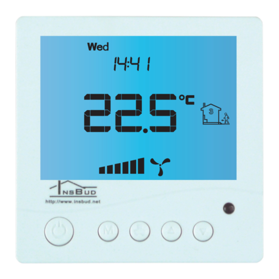
Page 8: Lcd Display
WWW.INSBUD.NET LCD display 1 - day of the week. 7 - visible symbol means manual mode. 2 - current ventilation level or information. 8 - time. 3 - visible symbol means keypad lock. 9 - time period. 4 - temperature or setting value. -
Page 9: Mounting
WWW.INSBUD.NET Mounting The controller wiring, led to the electrical installa- tion box, should be connected to appropriate termi- nals of the controller, according to the manual. Make the connections with power off. Separate the two parts of the main panel housing of the controller. -
Page 10: Connection Module
WWW.INSBUD.NET Connection module Connect the flat cable to the socket in the front part of the main panel. Connect the two parts of the controller, starting with the catches at the top of the controller and ending with the catches at the bottom. -
Page 11: Fan Digital Input
WWW.INSBUD.NET button is pressed and returns to the open position FAN digital input when the button is released (used, for example, on doorbells). Alternatively, one of the modes of ope- The controller is equipped with an additional digi- ration of the FAN input provides for connection of tal input FAN there can be connected e.g. -
Page 12: Connection - Zehnder Basic, Aeris 350 I 450 Standard, Itho Daalderop Aure Vent D250
WWW.INSBUD.NET 4 from Legrand switch - to L screw terminal Connection - Zehnder Ba- in controller sic, AERIS 350 i 450 8 from Legrand switch - to N screw terminal in controller STANDARD, ITHO Daal- 7 from Legrand switch (if connected) - to N... - Page 13 WWW.INSBUD.NET...
-
Page 14: Connection - Low Voltage Cable
WWW.INSBUD.NET power supply is not available, use a low voltage con- Connection - low voltage troller. Below is an example of connection. cable 1 - main panel If there is a low voltage cable between the AHU and 2 - connection module 3 - low voltage cable, e.g. -
Page 15: Installation Notes
WWW.INSBUD.NET With the controller off, press and hold the M Installation notes button for about 3 seconds. The main panel together with the connection modu- The controller is in the configuration mode. Menu, le is usually installed in a generally accessible room, setting number, setting label, setting value and unit e.g. - Page 16 WWW.INSBUD.NET CFG = 1 Ventilation level 1 Ventilation level 2 Ventilation level 3 Possible to set from the controller Relay output states The above settings means: it is not possible to switch the AHU off from the controller (it is not possible to set „off” value in the operating schedule or in the manual mode).
-
Page 17: Fan Input Operation
WWW.INSBUD.NET CFG = 6 Ventilation level 1 Ventilation level 2 Ventilation level 3 Possible to set from the controller Relay output states To set the appropriate output signal standard: possibility to switch off). The sequence is repe- ated. If the controller operates in manual mode (MANUAL), pressing an additional button cau- Enter the configuration menu. -
Page 18: Ventilation Time
WWW.INSBUD.NET ton is pressed in ventilate mode or when the switch pressed. A larger value gives the user more time to is shorted in ventilation level override mode. To set enter settings. the temporary ventilation level: To set the idle time: Enter the configuration menu.Press the M... -
Page 19: Temperature Unit
WWW.INSBUD.NET To set the intensity of the backlight when the con- Set the number of days after which the filter troller is inactive: change reminder is activated or set „OFF” to disable the reminder. Exit the configuration menu or move to another setting. -
Page 20: Time And Day Of The Week
WWW.INSBUD.NET To enable/disable the keypad lock: Time and day of the week Press and hold for about 3 seconds both keys: To set the current time and day of the week: DOWN and UP simultaneously. Turn on the controller. Operating schedule... -
Page 21: Manual Mode
WWW.INSBUD.NET Press and hold the P button for about 3 se- When the controller is in the manual mode, the conds. The display will show PROG and the display shows the hand symbol and no time pe- current day of the week will start flashing. -
Page 22: Semi-Automatic Mode
WWW.INSBUD.NET and a beep sounds (also when the controller is turned Semi-automatic mode off). Po przeczyszczeniu lub wymianie filtra sygna- lizacja powinna ustąpić. After cleaning or replacing In semi-automatic mode, the ventilation level for the the filter the indication should stop. - Page 23 WWW.INSBUD.NET improper installation or operation, as well as pair, the costs of sending the equipment to and operation inconsistent with the intended use from the service shall be borne by the Custo- and operating instructions. The warranty does mer. not apply if the customer makes unauthorized...
Need help?
Do you have a question about the IB-Tron 3100FAN-230V and is the answer not in the manual?
Questions and answers