Table of Contents
Advertisement
Quick Links
Advertisement
Table of Contents

Related Manuals for AbsolutAire UC-3 HTLV

Summary of Contents for AbsolutAire UC-3 HTLV
- Page 1 UC-3 HTLV User Guide © 2022 AbsolutAire, Inc. 010622...
-
Page 2: A Note About Custom Designs
A Note About Custom Designs AbsolutAire often builds equipment with special features as requested by the customer. This manual only covers standard features and does not include any changes made for special feature requests by the customer. 010622... -
Page 3: Table Of Contents
Table of Contents A Note About Custom Designs Introduction Operation Schedule Menu Tree Main Display Quick Access Set Points Status Schedule Alarms Config Advanced Menu Network Integration Images Warning HMI Screen Information Sensor Alarm Display Tables Network Points List 010622... -
Page 4: Introduction
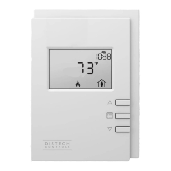
Introduction The Smart-Vue User Interface (UI) for the UC-3 HTLV Control System displays the information necessary to operate and diagnose the Heating and Ventilating Unit. This is connected to the controller via a CAT-5E cable with a maximum length of 600 feet. -
Page 5: Sensor Alarm Display
To turn the unit on or off, press the “up arrow” to access the Fan Command. Use the “up arrow” to select the desired option, then press the center button “menu” to return to the main display. To change set points such as temperature or building pressure, press the “menu”... -
Page 6: Schedule
The “SCHEDULE” will be described later. This is a 7-day occupancy schedule used for the purpose of temperature or operation changes during unoccupied times. The “CONFIG” menu is where the primary operating set points for the unit are set such as the minimum and maximum allowable discharge temperatures, as well as other items. - Page 7 Special events are used to override the weekly schedule and either keep a facility occupied for an event such as inventory or an important meeting, or to keep a facility unoccupied on a holiday when the building will remain empty. To program special events, press the “menu”...
-
Page 8: Menu Tree
Menu Tree When viewing menu tree options, the standard convention is: Point Name (as listed on the HMI) [BACnet ID] R or R/W (read only or read/write). Example: Space Temp [AV33] R Main Display Space Temp [AV33] R – Current space temperature at the User Interface (or remote space temperature sensor if equipped). -
Page 9: Schedule
Schedule (only visible if the unit has scheduling) Manual Occupancy - Allows the ability to force Occupied or Unoccupied modes, or to have the system follow the programmed schedule. Weekly Schedule Day of Week – Schedule day to be programmed. Occ Hour –... -
Page 10: Alarms
Alarms (alarm menu is only visible if an alarm is present) Space Sensor [MSV8] R – Space sensor alarm status. Enumerated “no-fault/open/short”. Check sensor wiring. Outside Sensor [MSV9] R – Outside sensor alarm status. Enumerated “no-fault/open/short”. Check sensor wiring. Discharge Sensor [MSV10] R – Discharge sensor alarm status. Enumerated “no-fault/open/short”. -
Page 11: Config
Config Heat Lockout [AV59] R/W – Heating mild weather stat setting. When the outside or mixed air temperature is above this setting the burner will be automatically disabled (only available if the unit has mild weather stat as an option). Control Deadband [AV58] R/W - Space temperature deadband for cycle on/off... -
Page 12: Network Integration
Network Integration The controller in this unit can easily be integrated into a BACnet MS/TP Building Management System. The controller will automatically detect the baud rate of the network it is connected to after a power cycle, and will automatically begin communications. The MAC Address is set via the dip switches on the front of the controller. -
Page 13: Network Points List
010622... - Page 14 (This page intentionally left blank for notes) 010622...
Need help?
Do you have a question about the UC-3 HTLV and is the answer not in the manual?
Questions and answers