
Summary of Contents for Parker Sea Recovery ULTROClear Series
- Page 1 Part Number: TM-UC1200-2400 REV B ULTROClear 1200-2400 GPD 4.5-9.8 m Installation, Operation & Maintenance...
- Page 2 Intentionally left blank...
-
Page 3: Revision History
REVISION HISTORY DATE DESCRIPTION AUTHOR April 27, 2018 Initial Release Paul K. May 16, 2019 Updated drawings S. Lentz... - Page 4 The following are the types of flags used in this technical manual. They designate safety related items and important operational instructions and should be given special attention when they appear in the text: Text formatted in this manner concerns an operating procedure or practice WARNING that, if not strictly observed, can result in injury to personnel or loss of life.
-
Page 5: System Description
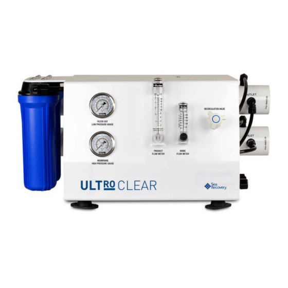
SYSTEM DESCRIPTION The Parker Hannifin UltRO Clear System is a purification system that uses direct feed water from Sea water RO unit or Dock water to produce spot free ultra-pure water. This unit produces UltRO Clear quality water with salt concentrations of <20 PPM TDS ppm by removing approximately 99% of the dissolved salt in potable water. -
Page 6: Physical Characteristics
1.1.2 PHYSICAL CHARACTERISTICS RO System Inch (mm) Length 28” (716) Width 18.9” (479) 17.4” (443) Height Table 1.1 - Unit Dimensions ULTRO CLEAR SYSTEM Weight 140 lbs. / 63.5 kg Table 1.2– Unit Weights 1.1.3 UTILITY REQUIREMENTS See the nameplate attached to top of the unit for power requirements. Motor Pump 0.33 0.25... -
Page 7: Environmental Requirements
Design Pressure Design Pressure Utility Connection Minimum Maximum BAR (psi) BAR (psi) Potable Water Feed ½ MNPT TUBE 8.62 1.4 (20) (125) Concentrate flow* ½ MNPT TUBE 8.62 0 (0) (reject discharge) (125) ½ MNPT TUBE 8.62 Product water flow* 0 (0) (125) * Vacuum condition at shutdown is not acceptable, syphon breaker may be required. -
Page 8: Test Equipment
1.2.1 CONSUMABLES The following is the normal quantity of equipment consumed during 6 months of standard unit operation: NOTE Only Parker approved filters and chemicals should be used. Description Parker Part No. Pre-filter sediment/carbon: 0803004773 * See pump technical manual for special tools. -
Page 9: Unpacking And Handling
CAUTION Do not allow unit or any components to be exposed to freezing temperatures. If it is anticipated that the unit may be exposed to freezing temperature, please contact Parker in advance for technical assistance. LOCATION The RO unit should be installed in a dry, sheltered location protected from direct weather. - Page 10 CAUTION Inlet and discharge interconnecting lines should be constructed of a NON-FERROUS material. Examples of some suitable materials are PVC, copper-nickel, 316 stainless steel pipe or a reinforced non-collapsing hose. Ferrous piping produces rust that will irreversibly foul the membrane and void the RO unit warranty.
-
Page 11: General Theory Of Operation
GENERAL THEORY OF OPERATION REVERSE OSMOSIS THEORY Reverse osmosis, like many other practical scientific methods, has been developed from processes first observed in nature. Osmosis is a naturally occurring phenomenon in which a semi-permeable membrane separates a pure and a concentrated solution (a semi-permeable membrane is defined as one that preferentially passes a substance). - Page 12 Potable water contains many kinds of solids dissolved in solution. The most prevalent is common table salt (sodium chloride). Other minerals that may be present in solution are substances that usually contain various compounds of calcium and sulfate. The sum of all the solids dissolved in a sample of water is referred to as Total Dissolved Solids or TDS.
- Page 13 The following table illustrates how the quality and quantity of permeate produced in by RO system is affected by changes in temperature, salinity and pressure: Permeate With constant..And increasing..Capacity Salinity and Pressure Temperature Increases Increases Temperature and Pressure Salinity Increases Decreases...
- Page 14 Example: Raw water temp: 15°C TCF: 1.47 Actual product flow: 113.5 (GPH) Calculation: 113.5 x 1.47 = 167 (GPH) Temperature Corrected flow: 167 (GPH) (167 GPH is the normal flow for a PW4000) °C Factor °C Factor °F Factor °F Factor 3.64 0.97...
- Page 15 3.4.1 ULTRO CLEAR SYSTEM Potable water supplied to the intake of the Parker RO ULTRO CLEAR unit will initially flow through the Relief Valve. This valve is set at 60 psi (4.15 Bar). Once through the relief valve, the potable water is supplied to the filtration system.
- Page 16 3.4.2 REVERSE OSMOSIS SYSTEM The clean and filtered raw water (now referred to as feedwater) is supplied to the inlet of the high-pressure pump, P-20. This pump raises feedwater pressure to 10.5 BAR (150 psi), the nominal pressure required for optimal system recovery. The pressurized feedwater then flows directly into the membrane array.
-
Page 17: Controls And Instrumentation
CONTROLS AND INSTRUMENTATION The following table provides a brief description of each individual component along with an explanation of its function. It is intended as a supplement to the more detailed information contained in Section 9.0 – System/Equipment Drawings and Diagrams. - Page 18 Figure 3.4– Major Components Location...
-
Page 19: Operation
OPERATION LOAD OUT PROCEDURE Load Carbon / Sediment filters into filter housing. See section 5.2 for detailed procedure. Load membrane into pressure vessel. See section 5.3. FIRST TIME START- PROCEDURE 1) Check the tightness of all lines and fittings. 2) Place the RO unit's valves and switches in the positions shown in Table 4.0. - Page 20 6) Inspect all plumbing connections in the unit for leakage. Temperature variations during shipment may cause plumbing connections to seep when initially started on-site. Secure the power to the unit and repair any leaks prior to proceeding. Once the leaks have been repaired, re-energize system and open the water source.
-
Page 21: Quick Start-Up Procedure
liters per hour (LPH) and gallons per hour (GPH) the reject flow rate from the RO array 227LPH (60 GPH). Record the reject flow after the first 5 hours of operation (use the sample Operational Log sheet provided in Figure 5.2). Press Stop button. -
Page 22: Maintenance Instructions
the unit will be secured for more than 14 days. Although they do not attack the membranes or other system components directly, high concentrations of biological matter can block enough of the product water channels to cause a reduction of as much as 40% of the total system capacity. - Page 23 2614010473 Table 5.1 - Filter Parts List. CAUTION Parker filter cartridges are specifically designed for RO applications and constructed with a carbon attractive chlorine. Use of non-approved cartridges will void the RO unit warranty. Replace the filter element(s) using the following procedure: Secure the RO unit.
- Page 24 MEMBRANE ELEMENT INSTALLATION OR REPLACEMENT The membrane when the pressure is at maximum and the TDS is unacceptable. Call Description Qty Parker Part # VESSEL, FRP,3021,1 KPSI, W/O ENDCAPS 50012002 ELEMENT, BRACKISH WATER, LE-3021 33-0321 VESSEL END PLUG, ACETAL,3021,1/4 FNPT PORTS...
-
Page 25: Pressure Vessel
Replace the membrane element(s) using the following procedure: PRESSURE VESSEL: Disassembly of the RO Membrane and Vessel Assembly: Remove the hoses and fittings from each end of the High-Pressure Vessel Assembly. Remove SC SOC CAP 1/4-20 X 3/4 SS #5, that hold the Segment Rings #9 in place. - Page 26 CAUTION At each end of the Reverse Osmosis Membrane Element is a Product Water Tube approximately 2 cm (¾”) diameter by 2.5 cm (1” long). The outside diameter surface of this product water tube is a sealing surface, which isolates the Product Water from the Feed Water. The surface of the Product Water Tube must be scratch free.
-
Page 27: Inspection Log
Insert the End Plug with new attached O-Rings into the High- Pressure Vessel while aligning the High-Pressure Port and Product Water Port to the respective holes in the High-Pressure Vessel. Continue pushing inward on the End Plug until its exposed end travels just past the Segment Ring Groove in the Pressure Vessel. - Page 28 PI-25, Product Total FI-40, FI-50 PI-20, W ater Membrane W ater Operating Reject Product Date Feed Comments Temp, Inlet Hours Flow Flow Pressure (°C) Pressure (ppm) Figure 5.1 - Sample Operational Log...
- Page 29 COMMENT/DISCREPANCY REPORT Parker Hannifin RO UltRO Clear Plant No: Date: Log Task No: Time: System Affected: Technician: Comment / Discrepancy: Corrective Action: Action Taken: Date Completed: Printed Name: Signature: Figure 5.2 - Sample Discrepancy Report...
-
Page 30: Troubleshooting
PRESERVATION FOR STORAGE When the Parker Hannifin RO unit is to be shut down for an extended period, it is necessary take steps to prevent the growth of biological organisms see Section 4.2 Shut Down Procedure. If the unit will at any time be exposed to air temperatures of 32°F (0°C) or less, the membranes must be removed and the unit fully drained or the... - Page 31 SYSTEM DRAWINGS AND DIAGRAMS AND PARTS LIST...
- Page 32 .0 [0] FOR ANY PURPOSE OTHER THAN CONDUCTING BUSINESS WITH PARKER, AND WILL BE RETURNED AND ALL FURTHER USE DISCONTINUED UPON REQUEST BY PARKER. THE RECIPIENT OF THIS DOCUMENT THROUGH ITS OWN ANALYSIS AND TESTING IS SOLELY RESPONSIBLE FOR MAKING THE FINAL SELECTION OF THE APPLICABLE SYSTEM AND COMPONENTS AND ASSURING THAT ALL PERFORMANCE, ENDURANCE, MAINTENANCE, SAFETY AND WARNING REQUIREMENTS OF THE APPLICATION ARE MET.
- Page 33 PARTS LIST ITEM PART NUMBER DESCRIPTION 0520051800-1 MVA RACK , UWDX BJ 05202401GR BRACKET,MVA U-CLAMP,3 IN 0861044 FRAME,ASSY,ZK SERIES 20201030000 SEGMENT RING AW (SET) 50012002 VESSEL, 3021 FRP 51012001 END PLUG, 3021, 1-4 IN PORTS 12176402DP PUMP ROTARY VANE 140 GPH #15 12227601DP COUPLING PUMP-MOTOR SHAFT 12227701DP...
- Page 34 FROM PRESSURE VESSEL ASSY FROM FILTER ASSY PI-20 FROM FEED WATER INLET ASSY AC-20A TO FEED WATER INLET ASSY PI-25 PS-50 FROM MOTOR ASSY FI-50 AC-20B GAUGES FROM MOTOR ASSY FI-40 TO FILTER ASSY TO MOTOR ASSY TO GAUGES FILTER ASSY FLOWMETER ASSY REJECT WATER FROM PRESSURE...
- Page 35 GAUGES - EXPLODED GAUGES FILTER ASSY FLOWMETER ASSY FLOWMETER ASSY - EXPLODED FILTER ASSY - EXPLODED MOTOR ASSY PRESSURE VESSEL ASSY FEED WATER INLET ASSY FEED WATER INLET ASSY - EXPLODED MOTOR ASSY - EXPLODED PRESSURE VESSEL ASSY - EXPLODED SIZE DWG NO UC1200-116...
- Page 36 FURNISHED ON THE UNDERSTANDING THAT THE DOCUMENT AND THE INFORMATION IT CONTAINS WILL NOT BE COPIED OR DISCLOSED TO OTHERS OR USED FOR ANY PURPOSE OTHER THAN CONDUCTING BUSINESS WITH PARKER, AND WILL BE RETURNED AND ALL FURTHER USE DISCONTINUED UPON REQUEST BY PARKER.
- Page 37 PARTS LIST ITEM PART NUMBER DESCRIPTION 0520051800-1 MVA RACK , UWDX BJ 05202401GR BRACKET,MVA U-CLAMP,3 IN 0861044 FRAME,ASSY,ZK SERIES 20201030000 SEGMENT RING AW (SET) 50012002 VESSEL, 3021 FRP 51012001 END PLUG, 3021, 1-4 IN PORTS 12176402DP PUMP ROTARY VANE 140 GPH #15 12227601DP COUPLING PUMP-MOTOR SHAFT 12227701DP...
- Page 38 TO FILTER ASSY FROM PRESSURE VESSEL ASSY FROM FEED WATER INLET ASSY AC-20A PRV-10 TO FEED WATER INLET ASSY PS-50 FROM FLOWMETER ASSY AC-20B TO MOTOR ASSY TO GAUGES FI-50 FROM MOTOR ASSY FILTER ASSY FI-40 FEED WATER FROM PRESSURE VESSEL ASSY PRODUCT WATER FEED WATER INLET ASSY...
- Page 39 GAUGES FILTER ASSY FLOWMETER ASSY FLOWMETER ASSY - EXPLODED FILTER ASSY - EXPLODED GAUGES - EXPLODED MOTOR ASSY PRESSURE VESSEL ASSY FEED WATER INLET ASSY FEED WATER INLET ASSY - EXPLODED PRESSURE VESSEL ASSY - EXPLODED MOTOR ASSY- EXPLODED SIZE DWG NO UC1200-215 SCALE...
- Page 40 FURNISHED ON THE UNDERSTANDING THAT THE DOCUMENT AND THE INFORMATION IT CONTAINS WILL NOT BE COPIED OR DISCLOSED TO OTHERS OR USED FOR ANY PURPOSE OTHER THAN CONDUCTING BUSINESS WITH PARKER, AND WILL BE RETURNED AND ALL FURTHER USE DISCONTINUED UPON REQUEST BY PARKER.
- Page 41 PARTS LIST ITEM PART NUMBER DESCRIPTION 0520051800-1 MVA RACK , UWDX BJ 05202401GR BRACKET,MVA U-CLAMP,3 IN 0861044 FRAME,ASSY,ZK SERIES 20201030000 SEGMENT RING AW (SET) 50012002 VESSEL, 3021 FRP 51012001 END PLUG, 3021, 1-4 IN PORTS 12176402DP PUMP ROTARY VANE 140 GPH #15 12227601DP COUPLING PUMP-MOTOR SHAFT 12227701DP...
- Page 42 FROM PRESSURE VESSEL ASSY FROM FEED WATER INLET ASSY MEMBRANE VESSEL AC-20A TO FLOWMETER ASSY TO FEED WATER INLET ASSY PS-50 AC-20B TO MOTOR ASSY PRESSURE VESSEL ASSY TO GAUGES FI-50 FROM MOTOR FI-40 ASSY FILTER ASSY TO FILTER ASSY FLOWMETER ASSY TO MOTOR ASSY FROM MOTOR ASSY...
- Page 43 GAUGES GAUGES - EXPLODED FILTER ASSY FLOWMETER ASSY FLOWMETER ASSY - EXPLODED FILTER ASSY - EXPLODED PRESSURE VESSEL ASSY MOTOR ASSY FEED WATER INLET ASSY PRESSURE VESSEL ASSY - EXPLODED SIZE DWG NO MOTOR ASSY - EXPLODED UC2400-116 FEED WATER INLET ASSY - EXPLODED SCALE...
- Page 44 FURNISHED ON THE UNDERSTANDING THAT THE DOCUMENT AND THE INFORMATION IT CONTAINS WILL NOT BE COPIED OR DISCLOSED TO OTHERS OR USED FOR ANY PURPOSE OTHER THAN CONDUCTING BUSINESS WITH PARKER, AND WILL BE RETURNED AND ALL FURTHER USE DISCONTINUED UPON REQUEST BY PARKER.
- Page 45 PARTS LIST ITEM PART NUMBER DESCRIPTION 0520051800-1 MVA RACK , UWDX BJ 05202401GR BRACKET,MVA U-CLAMP,3 IN 0861044 FRAME,ASSY,ZK SERIES 20201030000 SEGMENT RING AW (SET) 50012002 VESSEL, 3021 FRP 51012001 END PLUG, 3021, 1-4 IN PORTS 12176402DP PUMP ROTARY VANE 140 GPH #15 12227601DP COUPLING PUMP-MOTOR SHAFT 12227701DP...
- Page 46 FROM PRESSURE VESSEL ASSY FROM FEED WATER MEMBRANE VESSEL INLET ASSY AC-20A TO FLOWMETER ASSY TO FEED WATER INLET ASSY PS-50 AC-20B TO MOTOR ASSY TO GAUGES FI-50 PRESSURE VESSEL ASSY FI-40 FROM MOTOR ASSY FILTER ASSY FLOWMETER ASSY TO FILTER ASSY TO MOTOR ASSY FROM MOTOR ASSY REJECT WATER...
- Page 47 GAUGES - EXPLODED GAUGES FILTER ASSY FLOWMETER ASSY FLOWMETER ASSY - EXPLODED FILTER ASSY - EXPLODED PRESSURE VESSEL ASSY MOTOR ASSY FEED WATER INLET ASSY PRESSURE VESSEL ASSY - EXPLODED SIZE DWG NO UC2400-215 MOTOR ASSY - EXPLODED FEED WATER INLET ASSY - EXPLODED SCALE...
- Page 48 FURNISHED ON THE UNDERSTANDING THAT THE DOCUMENT AND THE INFORMATION IT CONTAINS WILL NOT BE COPIED OR DISCLOSED TO OTHERS OR USED FOR ANY PURPOSE OTHER THAN CONDUCTING BUSINESS WITH PARKER, AND WILL BE RETURNED AND ALL FURTHER USE DISCONTINUED UPON REQUEST BY PARKER.
- Page 49 PARTS LIST ITEM PART NUMBER DESCRIPTION 05202401GR BRACKET,MVA U-CLAMP,3 IN 0861044 FRAME,ASSY,ZK SERIES 11012179 RACK,MVA,3 VESSEL,AL 20201030000 SEGMENT RING AW (SET) 50012002 VESSEL, 3021 FRP 51012001 END PLUG, 3021, 1-4 IN PORTS 12176404DP PUMP ROTARY VANE 215GPH #17 12227601DP COUPLING PUMP-MOTOR SHAFT 12227701DP ADAPTER PUMP ROTARY VANE 1519071010...
- Page 50 FROM PRESSURE VESSEL ASSY FROM FEED WATER MEMBRANE VESSEL INLET ASSY TO MOTOR ASSY TO FEED WATER INLET ASSY AC-20A TO FLOWMETER ASSY PS-50 FI-50 FI-40 FROM MOTOR ASSY FLOWMETER ASSY AC-20B TO MOTOR ASSY PRESSURE VESSEL ASSY TO GAUGES REJECT WATER FROM PRESSURE FILTER ASSY...
- Page 51 GAUGES FLOWMETER ASSY - EXPLODED GAUGES - EXPLODED FILTER ASSY FLOWMETER ASSY FILTER ASSY - EXPLODED PRESSURE VESSEL ASSY MOTOR ASSY FEED WATER INLET ASSY MOTOR ASSY - EXPLODED SIZE DWG NO UC3400-116 FEED WATER INLET ASSY - EXPLODED PRESSURE VESSEL ASSY - EXPLODED SCALE...
Need help?
Do you have a question about the Sea Recovery ULTROClear Series and is the answer not in the manual?
Questions and answers