Table of Contents
Advertisement
Quick Links
Advertisement
Table of Contents

Related Manuals for KaVo 5650

Summary of Contents for KaVo 5650
- Page 1 Operating instructions Type 5650, 5651, 5652, 5653. Always on the safe side.
- Page 2 KaVo Elektrotechnisches Werk GmbH Wangener Straße 78 D-88299 Leutkirch Tel.: 0 75 61 / 86-150 • Fax: 0 75 61 / 86-265...
-
Page 3: Table Of Contents
Type 5650, 5651, 5652, 5653. User information ................................2 A 1.1 Meaning of the pictograms ............................2 A 1.2 Important information ..............................2 A 1.3 Precautions ................................2 Scope of delivery and accessories ..........................3 A 2.1 Scope of delivery ..............................3 2.2 Accessories ................................3 Mains voltage - Mains frequency ..........................3 A 3.1 Identification plate ..............................3... -
Page 4: A 1 User Information
Type 5650, 5651, 5652, 5653. A 1.2 Important information A 1.3 Precautions A 1 User information The instructions for use should be Safe operation and protection of the unit are A 1.1 Meaning of the pictograms read by the user before starting up the... -
Page 5: A 2 Scope Of Delivery And Accessories
Type 5650, 5651, 5652, 5653. A 2 Scope of delivery and accessories A 2.1 Scope of delivery Checking the completeness of the unit. Extraction canopy with fan unit type 5650 consisting of: 1 Extraction canopy 1200/700 2 Filter elements 2 Brackets... -
Page 6: A 4 Location
Type 5650, 5651, 5652, 5653. A 4 Location The extraction canopy can be installed above preheating furnaces, polymerisation units, waxing-out furnaces, boil-out units or other equipment. The canopy cannot be used for the extraction of explosive or aggressive vapours, e.g. from acids. -
Page 7: A 5 Mounting And Connection
Type 5650, 5651, 5652, 5653. A 5 Mounting and connection Remove the filter elements and set of screws (fitted to the compensation pan- ) from the extraction canopy Mark on the wall the envisaged extraction canopy´s upper edge of 2400 mm and its width of 1200 mm or 1800 mm. - Page 8 Type 5650, 5651, 5652, 5653. Hang the extraction canopy onto the brackets in the manner indicated by the arrrow. Link the connecting piece with the in- house exhaust-air ducting system and seal. The overall length of the exhaust-air duct should be as short as possible to achieve the highest extraction efficiency rates.
-
Page 9: A 6 Preparations For Commencing Operation
Type 5650, 5651, 5652, 5653. A 6 Preparations for commencing operation Plug the mains cable into an earthed power socket that is correctly fused. Press the start switch for the extraction fan into OFF "0" position. Press the mains switch into ON "I"... -
Page 10: A 7 Control And Functional Elements
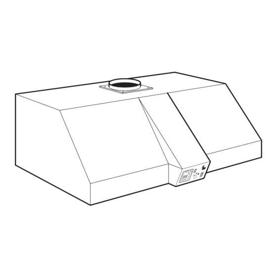
Type 5650, 5651, 5652, 5653. A 7 Control and functional ele- ments Extraction canopy Brackets (2 or 3) Filter elements (2 or 3) Control-Unit Panel with lead-through for cable Panel Fuse 100 V - 127 V, T 6.3 A delay-action 220 V - 240 V, T 3.15 A delay-action... -
Page 11: A 8 Operation
Type 5650, 5651, 5652, 5653. A 8 Operation A 8.1Manual operation (continuous operation) without time preselec- tion. Press the start switch for the extraction fan upwards into the "1" position. Adjust the desired extraction rate with the 3-speed extraction rate selector Press the mains switch into "I"... -
Page 12: A 8.3 Manual Operation While The Preselected Time Is Elapsing In "Automatic Operation
Type 5650, 5651, 5652, 5653. For every day of the week (1-7), at least details of the time or reset to "- - - -" must be made with the buttons I (blue and red) of the time preselector On delivery from the factory and also after... -
Page 13: A 9 Maintenance
Type 5650, 5651, 5652, 5653. A 9 Maintenance Repairs and servicing work on the electrical part of this equipment must only be undertaken by experts or by per- sons trained in our factory who are aware of the safety regulations. Disconnect the mains plug from the power supply, resp. -
Page 14: A 10 Operating Faults
Type 5650, 5651, 5652, 5653. A 10 Operating faults Repairs and servicing work on the electrical part of this equipment must only be undertaken by experts or by per- sons trained in our factory who are aware of the safety regulations. Disconnect the mains plug from the power supply, resp. -
Page 15: A 11 Technical Data
Type 5650, 5651, 5652, 5653. A 11 Technical data Dimensions with control-unit: type Width Height Depth 5650 1200 mm 400 mm 790 mm 5651 1800 mm 400 mm 790 mm 5652 1200 mm 400 mm 990 mm 5653 1800 mm... -
Page 16: Guarantee Conditions
Under valid KaVo EWL delivery and payment conditions, KaVo EWL gives a guarantee of satisfactory function and freedom from faults in material and manufacture for the duration of 6 months from the date of sale certified by the vendor. After expiry of the warranty, KaVo gives a guarantee of another 6 months for damage attributable to deficiencies in the material or in manufacture. -
Page 17: Declaration Of Conformity
Type 5650, 5651, 5652, 5653. -
Page 18: Spare Parts
Type 5650, 5651, 5652, 5653. 0.659.4861 0.659.3722 1 2 3 4 5 6 7 0.659.4541 IIII IIII 0.223.2329 0.223.2288 0.224.6661 0.659.9041 0.221.3181 0.658.5142 0.221.4380 0.658.5142 0.223.1011 100-127 V 0.223.1088 220-240 V 0.223.2800 T6 A 100-127 V 0.223.2741 T3,15 A 200-240 V... - Page 19 Type 5650, 5651, 5652, 5653.
- Page 20 D D - - 8 8 8 8 2 2 9 9 9 9 L L E E U U T T K K I I R R C C H H . . T T e e l l e e f f o o n n 0 0 7 7 5 5 6 6 1 1 / / 8 8 6 6 - - 1 1 5 5 0 0 · · F F a a x x 0 0 7 7 5 5 6 6 1 1 / / 8 8 6 6 - - 2 2 6 6 5 5 I I n n t t e e r r n n e e t t : : w w w w w w .
Need help?
Do you have a question about the 5650 and is the answer not in the manual?
Questions and answers