Table of Contents
Advertisement
Quick Links
Advertisement
Table of Contents

Related Manuals for mcmurdo C1 S-VDR


Summary of Contents for mcmurdo C1 S-VDR
- Page 1 C1 S-VDR Service Manual...
-
Page 3: Table Of Contents
All rights are strictly reserved. The information must not be used except for the agreed purpose. Unauthorised use, reproduction or issue to any third party is not permitted without the prior written authority of McMurdo Limited. This document is to be returned to McMurdo Limited when the agreed purpose is fulfilled. C1 S-VDR service manual... -
Page 5: Introduction
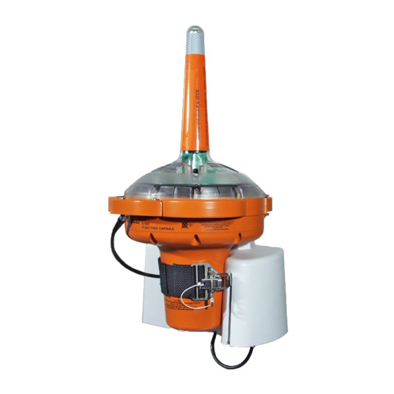
1.2 Applicability This information applies to the following S-VDR equipments: • 36-001-001A Firewire 6GB • 36-001-002A Ethernet 2GB • 36-001-003A Ethernet 6GB • 36-001-004A Firewire 9GB • 36-001-005A Ethernet 2GB C1 S-VDR service manual Issue 1 Page 1... - Page 6 S-VDR EPIRB in mount C1 S-VDR service manual Issue 1 Page 2...
-
Page 7: Servicing Equipment
As a minimum, the operator must be connected to a good earth point through a resistance of 1Mohm. This is usually achieved by wearing a suitable wrist strap. C1 S-VDR service manual Issue 1 Page 3... -
Page 8: Safety Notices
Do not attempt to discharge a leaking battery – remove it using appropriate handling materials and seal in a plastic bag, then dispose of it through an approved environmental disposal agent, or in accordance with local regulations. C1 S-VDR service manual Issue 1 Page 4... - Page 9 Read the manufacturer's instructions before using any chemical agent. Wear goggles Wear overalls Wash hands Wear gloves C1 S-VDR service manual Issue 1 Page 5...
-
Page 10: False Alarms
10 screws have to be removed and further internal damage may occur. If this has to be done, once the FFC is open then disconnecting the battery lead stops all activity. See section 3.5. C1 S-VDR service manual Issue 1 Page 6... -
Page 11: Assessment
EPIRB must be subjected to a full assessment before any other action is taken. The agent has a responsibility to ensure the EPIRB is completely serviceable and is fit for its purpose. C1 S-VDR service manual Issue 1 Page 7... -
Page 12: Assessment
The expiry date must be noted; if less than 6 months life remains, a battery change should be recommended to the customer. Opening the FFC for internal inspection is only required if a problem is found. C1 S-VDR service manual Issue 1 Page 8... - Page 13 Battery voltage Plastic damage Switch fault volts Comments New Parts Conclusions HRU kit Battery kit Top cone kit EPIRB PCB Lanyard Sealing Kit Assessed by Signed Date FINAL LEAK TEST Pass/Fail Other: C1 S-VDR service manual Issue 1 Page 9...
- Page 14 C1 S-VDR service manual Issue 1 Page 10...
-
Page 15: Maintenance Procedures
8. Examine the sea switch contacts on the bottom cone. If there are signs of rust, white powdery corrosion or salt deposits then the contacts must be cleaned. C1 S-VDR service manual Issue 1 Page 11... -
Page 16: Functional Tests
2. Press the ON switch. 3. Allow the strobe to flash three times 4. Press the Test button to switch the unit off. The unit should turn off within 2 seconds. Fit a new integrity seal. C1 S-VDR service manual Issue 1 Page 12... -
Page 17: Message Read
In this case the Reader reports NORMAL OK and the first 3 bytes of the full hex message are FF FE 2F… instead of the FF FE D0… for self test mode. C1 S-VDR service manual Issue 1 Page 13... -
Page 18: Internal Inspection
• Check top of circuit board for white salt deposits, dull grey corrosion or wetness. If any corrosion is evident the FFC should be completely disassembled. • Check plastic parts, especially screw positions, for signs of cracking and for possible leakage paths. C1 S-VDR service manual Issue 1 Page 14... -
Page 19: Disassembly
When it stops, re-tighten the TEST switch boot. Pull the cones apart. 3. Gently lift the top cone up taking great care not to damage the Reed switch PCB which extends into the DSM C1 S-VDR service manual Issue 1 Page 15... - Page 20 Removing the switches. The 2 off switches can be removed by undoing the switch boot using an 11mm driver. The switches are located in the plastic and cannot rotate. C1 S-VDR service manual Issue 1 Page 16...
Need help?
Do you have a question about the C1 S-VDR and is the answer not in the manual?
Questions and answers