Table of Contents
Advertisement
Quick Links
Advertisement
Table of Contents

Related Manuals for Video-Tech DPC-D248-R


Summary of Contents for Video-Tech DPC-D248-R
- Page 1 DPC-D248-R 2-wired door station User manual...
-
Page 2: Table Of Contents
Contents 1.Parts and Functions..................... 1 2.Mounting ......................1 3.Terminal Descriptions ..................2 4.System Wiring and Connections ................. 3 5. Functions Setting Up ..................9 6.Power Supply Instructions ................... 17 7. Precaustions ....................... 17 8.Specifications ...................... 17 9.Cables Requirements ..................18... -
Page 3: Parts And Functions
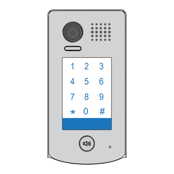
1.Parts and Functions Camera Lens Speaker Night Light Touch Sensitive Digital Keypad 28 mm Nameplate Call Button Rainy Cover Microphone 93 mm 2.Mounting Mounting Drill holes in the wall to match the size of Connect the cable correctly screws and attach the rainy cover to the wall. Attach the panel to the rainy cover Use the screwdriver and the screw to fix the panel... -
Page 4: Terminal Descriptions
Placing Name Label Use a screwdriver to unscrew the screw, and cock the host , then Placing Name Label. 3.Terminal Descriptions • Lock Control Jumper: To select the lock type. • Main Connect Port: To connect the bus line and the electronic locks. -
Page 5: System Wiring And Connections
4.System Wiring and Connections Basic Connection monitor L1 L2 PL S+ S- Electric Lock Connection Door Lock Controlled with Internal Power Note: Electronic lock of Power-on-to-unlock type should be used. The door lock is limited to 12V, and holding current must be less than 250mA. The door lock control is not timed from Exit Button(EB). - Page 6 Door Lock Controlled with Dry Contact Note: The external power supply must be used according Connect one lock to the lock. Take off the Jumper The inside relay contact is restricted to AC or DC 24V/1A. The jumper must be taken off before connecting. Setup the Unlock Mode of Monitor for different lock types.
- Page 7 Multi Door Stations Connection monitors DBC4 A B C D 85~260VAC 4# Camera 3# Camera 2# Camera 1# Camera (Device Address:3) (Device Address:2) (Device Address:1) (Device Address:0)
- Page 8 Multi Monitors Connection Basic IN-OUT Wiring Mode monitor 3 4 5 6 Code=15, DIP-6=on monitor 3 4 5 6 Code=14, DIP-6=off monitor 3 4 5 6 Code=0, DIP-6=off 85~260AC (Device Address:0)
- Page 9 With DBC4 Wiring Mode monitor monitor 3 4 5 6 3 4 5 6 Code=15, DIP-6=on Code=14, DIP-6=on monitor monitor 3 4 5 6 3 4 5 6 Code=12, DIP-6=on Code=13, DIP-6=on monitor monitor 3 4 5 6 3 4 5 6 Code=2, DIP-6=on Code=3, DIP-6=on monitor...
- Page 10 Extending Connections with DCU unit CALL CALL UNLOCK UNLOCK TALK/MON TALK/MON IN-USE IN-USE 3 4 5 6 3 4 5 6 Code=3, DIP-6=on Code=2, DIP-6=on CALL CALL UNLOCK UNLOCK TALK/MON TALK/MON IN-USE IN-USE 3 4 5 6 3 4 5 6 Code=1, DIP-6=on Code=0, DIP-6=on DCU Code =3(11)
-
Page 11: Functions Setting Up
5. Functions Setting Up This section explains the settings of each function,please refer to the following table: About the setting mode: Input the master code to switch to the setting mode, and input the corresponding setting code to perform the settings for the function you want. - Page 12 Order Setting items Setting range Default value Setting code Reset all settings 1234 1 ~ 12 digits Setting the master code 1234 Valid keys:0 ~ 9 Setting the key 10 to 99 seconds/ 10 seconds illumination time continually lit Setting the unlock time 01 to 99 seconds 1 seconds Setting the unlock mode...
- Page 13 Each operation is indicated by the lighting up of the different color of digital key and nameplate , and by the sounding of the buzzer. The color of key indicator Input the master code. (Default: [ ] +[#] ) (white) Beep+, Beep 1.Reset all settings 2.Setting the master code...
- Page 14 The color of key indicator Input the master code. (Default: [ ] +[#]) (white) Beep+, Beep 5.Setting the unlock mode 6.Setting operation tone 7.Reset code setting 8. &# function setting (Default 0(opened)) (Default ON) (Default Normal) Input the setting code. Input the setting code.
- Page 15 Input the master code. The color of key indicator (Default: [ ] +[#]) Beep+, Beep (white) 9. Call tone setting 10.Interference resistant 11.IMC volume adjust 12.SPK volume adjust grade setting setting setting (Default enable) (Default 2) (Default:7) (Default:4) Input the setting code. Input the setting code.
- Page 16 Input the master code. The color of key indicator (Default: [ ] +[#]) Beep+, Beep (white) 13. Display scene setting 14.Night light level 15.Device address setting setting (Default 0) (Default 4) (Default:0 ) Input the setting code. Input the setting code. Input the setting code.
- Page 17 Input the master code. The color of key indicator (Default: [ ]+[#] ) Beep+, Beep (white) 16.Setting the code 17.Setting the code 18.Setting the code 19.Setting the code forTemporary1 forTemporary2 for user group1 for user group2 20~59 60~99 Input the setting code. Input the setting code.
- Page 18 Input the master code. The color of key indicator (Default: [ ]+[#] ) Beep+, Beep (white) 20.Work mode setting 21.Call address setting (Default:villa:00,16; (Default:1/villa) a partment:00~31) Input the setting code. Input the setting code. 100+# 101+# The color of key indicator The color of key indicator (yellow) Beep+, Beep...
-
Page 19: Power Supply Instructions
6.Power Supply Instructions Name Discription Usage Power supply,85~260Vac input,24Vdc/3A Connect with multi doorstations or DPA-PS5-24V output,10 DIN modules multi monitors(up to 2 or above) Power supply,85~260Vac input,24Vdc/1A Connect with one doorstation and one DPA-PS4-24V output,for basic kit only,4 DIN modules monitor(DPM-D235 can be connected two) 7. -
Page 20: Cables Requirements
9.Cables Requirements The maximum distance of the wiring is limited in the DT system. Using different cables may also affect the maximum distance which the system can reach. The farest monitor monitor with two or four monitors monitor monitor DBC/DBC-4 When Monitor quantity <...
Need help?
Do you have a question about the DPC-D248-R and is the answer not in the manual?
Questions and answers