Table of Contents
Advertisement
Quick Links
Instruction manual
Instruction manual
Operating & Maintenance
Operating & Maintenance
4812165301.pdf
4812165301.pdf
Vibratory roller
Vibratory roller
CA3500DCP
CA3500DCP
Cummins F 3.8 (Stage V)
Cummins F 3.8 (Stage V)
Serial number
Serial number
10000199xxA032445 -
10000199xxA032445 -
Translation of original instruction
Translation of original instruction
Reservation for changes
Reservation for changes
Printed in Sweden
Printed in Sweden
Engine
Engine
Advertisement
Table of Contents

Related Manuals for Dynapac CA3500DCP

Summary of Contents for Dynapac CA3500DCP
- Page 1 Instruction manual Instruction manual Operating & Maintenance Operating & Maintenance 4812165301.pdf 4812165301.pdf Vibratory roller Vibratory roller CA3500DCP CA3500DCP Engine Engine Cummins F 3.8 (Stage V) Cummins F 3.8 (Stage V) Serial number Serial number 10000199xxA032445 - 10000199xxA032445 - Translation of original instruction...
-
Page 3: Table Of Contents
Table of Contents Introduction ..........................1 The machine ....................1 Intended use ....................1 Training ....................... 1 Signal symbols and meaning ..............2 Safety information ..................2 General ....................... 3 CE marking and Declaration of conformity..........4 Safety - General instructions....................5 Safety - when operating ...................... - Page 4 Dimensions, top view ................17 Dimensions, compaction plates ..............18 Weights and volumes................18 Working capacity..................19 Compaction plate technical data ............... 19 General ..................... 20 -emission.................... 20 Fluid filled tires (Ballasted tires)..........21 Hydraulic system..................21 Air Conditioning / Automatic Climate Control (ACC) (Optional) ....22 Tightening torque ..................
- Page 5 DEF-displays (Urea quality) ..............45 DEF displays (EAT - Tampering) .............. 46 DEF displays (Exhaust cleaning lamp) ............. 47 DEF displays (Exhaust cleaning lamp disabled (inhibit) ......48 Dynapac Sub System (DSS)..............49 "MAIN MENU" ................... 49 "USER SETTINGS" ..............49 "MACHINE SETTINGS".............. 50 "SERVICE MENU"...
- Page 6 Electrical system...................... 59 Fuses in the main switchbox..............60 Fuses at the master switch............... 61 Fuse box at master switch ................ 61 Electricity for Urea system ................ 62 Fuses in cab....................62 Operation ..........................63 Before starting ......................63 Master switch - Switching on..............
- Page 7 Seismic - (Optional)................... 74 Adjustable (Variable) frequency - (Optional) ..........75 Dynapac Compaction Meter (DCM) including Active Bouncing Control (ABC) - Optional..................76 Setting limit....................77 Operation CMV ..................78 Connecting/disconnecting compaction plates ............78 Before connecting/disconnecting compaction plates ........ 78 Preparation for connection ................
- Page 8 Tires (All-weather)..................91 Hoods, tarpaulin ..................92 Urea tank (DEF tank) ................92 Miscellaneous ........................93 Lifting ........................93 Locking the articulation ................93 Lifting the roller..................93 Lifting the roller with jack:................94 Unlocking the articulation ................94 Towing/Recovering....................94 Short distance towing with the diesel engine switched off/not running ..
- Page 9 Every 2000 hours of operation ..............110 Every other year..................111 Maintenance, 10h ........................ 113 Scrapers - Check, adjustment..............113 Scrapers, Pad-drum ................114 Scrapers (Heavy duty), Pad drum............114 Flexible scrapers (Optional) ..............115 Air circulation - Check ................115 Coolant level - Check ................
- Page 10 Radiator - Check/Cleaning ..............128 Rubber elements and fastening screws - Check........128 Battery - Check condition ..................129 Air conditioning (Optional) - Inspection....................129 Automatic Climate Control (Optional) - Inspection ........130 Maintenance measures - 500 h ................... 131 Drum cartridge - Checking the oil level ...........
- Page 11 Air cleaner - Cleaning....................143 Rear axle differential - Oil change............144 Rear axle planetary gear - Oil change ............ 144 Drum gearbox - Oil change ..............145 Radiator - Check/Cleaning ..............145 The engine fuel filter - replacement/cleaning .......... 146 Diesel engine - Oil and Filter change ............
- Page 12 Seat bearing - Lubrication ............... 161 Hydraulic reservoir - Draining..............161 Fuel tank - Draining (Optional) ..............162 Air conditioning (Optional) Fresh air filter - Change ................162 Automatic Climate Control (Optional) - Overhaul ....................163 Drying filter - Check................. 163 Steering hitch - Tightening ..............
-
Page 13: Introduction
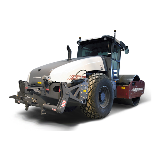
Introduction Introduction The machine The Dynapac CA3500DCP is a soil compactor that is factory-prepped and adapted for use with external auxiliary equipment in the form of vibrating compaction plates. The compatible compaction plates are Stehr SBV 80HC3 with accompanying side shift adjustment equipment in a low-profile design. -
Page 14: Signal Symbols And Meaning
Introduction Signal symbols and meaning WARNING ! Indicates potential hazardous WARNING ! Indicates potential hazardous situation/procedure which, if not avoided, could situation/procedure which, if not avoided, could result in death or serious injury. result in death or serious injury. CAUTION ! Indicates potential hazardous CAUTION ! Indicates potential hazardous situation/procedure which, if not avoided, could situation/procedure which, if not avoided, could... -
Page 15: General
Introduction CALIFORNIA Proposition 65 Decal and location of decal shown in section Machine description. General This manual contains instructions for machine operation and maintenance. The machine must be correctly maintained for maximal performance. The machine should be kept clean so that any leakages, loose bolts and loose connections are discovered at as early a point in time as possible. -
Page 16: Ce Marking And Declaration Of Conformity
Introduction by the machine operator. Other maintenance intervals must be carried out by accredited (Dynapac) service personnel. Additional instructions for the engine can be Additional instructions for the engine can be found in the manufacturer's engine manual. found in the manufacturer's engine manual. -
Page 17: Safety - General Instructions
Never jump down from the machine. • • Dynapac always recommends mounted ROPS (Roll Over Protective Dynapac always recommends mounted ROPS (Roll Over Protective Structure), or a ROPS-approved cab and seat belt usage. Structure), or a ROPS-approved cab and seat belt usage. - Page 18 Modifications to the roller, including the use of any attachment/equipment, Modifications to the roller, including the use of any attachment/equipment, not approved by Dynapac that might compromise safety (including visibility) not approved by Dynapac that might compromise safety (including visibility) are not allowed.
-
Page 19: Safety - When Operating
Safety - when operating Safety - when operating Prevent persons from entering or remaining in Prevent persons from entering or remaining in the risk zone, i.e. a distance of at least 7 m (23 the risk zone, i.e. a distance of at least 7 m (23 ft) in all directions from operating machines. -
Page 20: Work Driving
Dynapac always recommends mounted ROPS Dynapac always recommends mounted ROPS (Roll Over Protective Structure), or a (Roll Over Protective Structure), or a ROPS-approved cab and seat belt usage. -
Page 21: Safety (Optional)
Safety (Optional) Safety (Optional) Air conditioning The system described in this manual is an AC/ACC type (Automatic climate control) The system contains pressurized refrigerant. It is The system contains pressurized refrigerant. It is forbidden to release refrigerants into the forbidden to release refrigerants into the atmosphere. - Page 22 Safety (Optional) 4812165301.pdf 2022-09-02...
-
Page 23: Special Instructions
Special instructions Special instructions Standard lubricants and other recommended oils and fluids Before leaving the factory, the systems and components are filled with the oils and fluids specified in the lubricant specification. These are suitable for ambient temperatures in the range -15°C to +40°C (5°F - 105°F). -
Page 24: Fire Fighting
Special instructions with a rubber band. This is to avoid high pressure water entering the vent hole in the filler cap. This could cause malfunctions, such as the blocking of filters. Place a plastic bag over the exhaust pipe and secure with a rubber band to avoid water in the muffler. -
Page 25: Jump Starting (24V)
Special instructions Dispose of old batteries in an environmentally Dispose of old batteries in an environmentally friendly way. Batteries contain toxic lead. friendly way. Batteries contain toxic lead. Do not use a quick-charger for charging the Do not use a quick-charger for charging the battery. - Page 26 Special instructions 4812165301.pdf 2022-09-02...
-
Page 27: Technical Specifications
Technical specifications Technical specifications Vibrations - Operator station (ISO 2631) The vibration levels are measured in accordance with the operational cycle described in The vibration levels are measured in accordance with the operational cycle described in EU directive 2000/14/EC on machines equipped for the EU market, with vibration switched EU directive 2000/14/EC on machines equipped for the EU market, with vibration switched on, on soft polymer material and with the operator’s seat in the transport position. -
Page 28: Dimensions, Side View
Technical specifications Dimensions, side view Dimensions Dimensions Wheelbase, drum and wheel Wheelbase, drum and wheel 2990 2990 Length, lifting arms in transport position Length, lifting arms in transport position 6350 6350 Length, lifting arms in work position Length, lifting arms in work position 6490 6490 Length, with compaction plates (work position) -
Page 29: Dimensions, Top View
Technical specifications Dimensions, top view Dimensions Dimensions Width, front Width, front 2304 2304 Width, compaction plates Width, compaction plates 2120 2120 83.5 83.5 Wheel width Wheel width 2134 2134 Overhang, left frame side Overhang, left frame side Overhang, right frame side Overhang, right frame side Turn radius, external Turn radius, external... -
Page 30: Dimensions, Compaction Plates
Service weight CA3500DCP CA3500DCP 12 100 12 100 (kg) (kg) 26 680 26 680 (lbs) (lbs) CA3500DCP (with lifting arms) CA3500DCP (with lifting arms) 12 940 12 940 (kg) (kg) 28 530 28 530 (lbs) (lbs) CA3500DCP (with compaction plates) -
Page 31: Working Capacity
Technical specifications Working capacity Compaction data Compaction data Static linear load Static linear load CA3500DCP (with lifting arms) CA3500DCP (with lifting arms) 34,2 (kg/cm) 34,2 (kg/cm) 192 (pli) 192 (pli) CA3500DCP (with compaction plates) CA3500DCP (with compaction plates) Transport mode... -
Page 32: General
Technical specifications CA3500DCP CA3500DCP Propulsion Propulsion ATC (AntiSpin) ATC (AntiSpin) Speed range Speed range km/h (mph) km/h (mph) 0-12 (0-7.5) 0-12 (0-7.5) Climbing capacity Climbing capacity (theoretical) without (theoretical) without vibration, forward vibration, forward General Engine Engine Manufacturer/Model Manufacturer/Model Cummins F 3.8 (V/T4F) Cummins F 3.8 (V/T4F) -
Page 33: Fluid Filled Tires (Ballasted Tires)
Technical specifications Tire Tire Tire dimensions Tire dimensions Tire pressure Tire pressure Std type Std type 23.1 x 26.0 - 12 ply 23.1 x 26.0 - 12 ply 150-170 kPa (1,5-1,7 kp/cm) 150-170 kPa (1,5-1,7 kp/cm) (21,24 psi) (21,24 psi) Tractor type Tractor type 23.1 x 26.0 - 12 ply... -
Page 34: Air Conditioning / Automatic Climate Control (Acc) (Optional)
Technical specifications Air Conditioning / Automatic Climate Control (ACC) (Optional) The system described in this manual is an AC/ACC type (Automatic Climate Control). ACC is a system that maintains the set temperature in the cab, provided windows and doors are kept closed. The system contains fluorinated greenhouse gases. -
Page 35: Tightening Torque
Technical specifications Tightening torque Tightening torque in Nm for oiled or dry bolts tightened with a torque wrench. Metric coarse screw thread, bright galvanized (fzb): PROPERTY CLASS: 8.8, Oiled 8.8, Oiled 8.8, Dry 8.8, Dry 10.9, Oiled 10.9, Oiled 10.9, Dry 10.9, Dry 12.9, Oiled 12.9, Oiled... - Page 36 Technical specifications 4812165301.pdf 2022-09-02...
-
Page 37: Machine Description
Machine description Machine description Diesel engine The machine is equipped with a water-cooled, straight four cylinder, four-stroke, turbocharged diesel engine with direct injection and a charge air cooler. (Stage V) The engine is also equipped with a Cummins ® diesel oxidation catalyst, a diesel particulate filter and a selective catalytic reduction (DOC/DPF and SCR) system for exhaust gas aftertreatment. -
Page 38: Vibration System
FOPS/ROPS structure must be replaced immediately. Never perform any modifications on the cab or FOPS/ROPS structure without first having discussed the modification with Dynapac's production unit. Dynapac determines whether the modification could result in the approval according to the FOPS/ROPS standards becoming invalid. -
Page 39: Identification
Machine description Identification Product and component plates 1, 2 Product plate - Product Identification Number (PIN), model/type designation Product plate - Product Identification Number (PIN), model/type designation Engine plate - Type description, product and serial numbers Engine plate - Type description, product and serial numbers Cab/ROPS plate - Certification, product and serial numbers Cab/ROPS plate - Certification, product and serial numbers Component plate, rear axle - Product and serial numbers... -
Page 40: Machine Plate
Machine description Machine plate The machine type plate (1) is attached to the front left side of the frame, beside the steering joint. The plate specifies the manufacturer's name and address, the type of machine, the PIN product identification number (serial number), service weight, engine power and year of manufacture. -
Page 41: Engine Plates
Machine description Engine plates The engine type plates (1) are affixed to the top and on the right side of the engine. The plates specify the type of engine, serial number and the engine specification. Please specify the engine serial number when ordering spares. -
Page 42: Decals
Machine description Decals Location - decals 15,16 17,23 Fig. Location, decals and signs 1. Warning, Crush zone 1. Warning, Crush zone 4700903422 4700903422 12. Master switch 12. Master switch 4700904835 4700904835 2. Warning, Rotating engine 2. Warning, Rotating engine 4700903423 4700903423 13. -
Page 43: Location - Decals, California
Machine description Location - decals, CALIFORNIA Proposition 65 Warning, CALIFORNIA Warning, CALIFORNIA 4812129673 4812129673 Proposition 65 Proposition 65 Fig. Location Safety decals Always make sure that all safety decals are completely legible, and remove dirt or order new decals if they have become illegible. - Page 44 Machine description 4700904895 Warning - Brake disengagement Study the towing chapter before disengaging the brakes. Danger of being crushed. 4700903459 Warning - Instruction manual The operator must read the safety, operation and maintenance instructions before operating the machine. 4700903985 Warning - Ballasted tire. Read the instruction manual.
- Page 45 Machine description 4812129673 Warning CALIFORNIA - Proposition 65 2022-09-02 4812165301.pdf...
-
Page 46: Info Decals
Machine description Info decals Sound power level Sound power level Lifting point Lifting point 4700791275 4700791275 4700588176 4700588176 Hoisting plate Hoisting plate Handbook compartment Handbook compartment Master switch Master switch 4700904870 4700904870 4700903425 4700903425 4700904835 4700904835 Hydraulic fluid Hydraulic fluid Biological hydraulic fluid Biological hydraulic fluid Securing point... -
Page 47: Instruments/Controls
Machine description Instruments/Controls Control panel and controls Fig. Control panel Ignition switch Ignition switch Adjustable frequency/Seismic, Adjustable frequency/Seismic, Parking brake Parking brake On/Off On/Off Forward & Reverse lever Forward & Reverse lever Working mode / Transport Working mode / Transport Hazard lights Hazard lights mode... -
Page 48: Function Descriptions
Machine description Function descriptions Designation Designation Symbol Symbol Function Function Ignition key Ignition key The electric circuit is broken. The electric circuit is broken. All instruments and electric controls are supplied with All instruments and electric controls are supplied with power. - Page 49 Machine description Designation Designation Symbol Symbol Function Function Amplitude selector, high amplitude Amplitude selector, high amplitude Activation produces high amplitude. (Low amplitude is Activation produces high amplitude. (Low amplitude is the basic mode if the button is not activated.) the basic mode if the button is not activated.) Auto traction control, TC Auto traction control, TC If the machine is equipped with TC (Anti-spin), it is...
-
Page 50: Warning Indication - Membrane Panel (Keypad)
Machine description Designation Designation Symbol Symbol Function Function Parking brake Parking brake To activate the brakes, press the top of the switch to To activate the brakes, press the top of the switch to change the position of the switch. change the position of the switch. -
Page 51: Display Explanations
Machine description Display explanations When the ignition key is activated to position I, a start screen is visible in display. This is shown for a few seconds and then switches over to the status screen. Before activating the starter motor, wait until the start image has changed to the status image (the machine is performing a system check while the start image is being displayed). - Page 52 Machine description A menu field is shown by pressing one of the menu select buttons. The field is visible for a short while, if no selection is made the field fades out. Menu field will appear again upon pressing either one of the selection buttons (1).
- Page 53 Machine description A display for the compaction value (CMV value) can also be shown when the compaction meter (Option) is installed on the machine. Further information on this accessory is given in the Chapter "Operation". Fig. Compaction meter display (CMV display) When an engine alarm is activated, the alarm is shown on the display.
-
Page 54: Machine Alarm
Machine description Machine alarm Symbol Symbol Designation Designation Function Function Warning symbol, hydraulic fluid filter Warning symbol, hydraulic fluid filter If the symbol is shown when the diesel engine is running at If the symbol is shown when the diesel engine is running at full speed, the hydraulic fluid filter must be changed. - Page 55 Machine description Alarms received are logged and can be seen by selecting Display alarms. Inactive faults disappear from the log when you restart the ignition. Selection of Display alarms. "ENGINE ALARM" Logged engine alarms. Stored in the engine ECU. "MACHINE ALARM" Logged machine alarms.
-
Page 56: Def-Displays (Urea Tank Level)
Machine description DEF-displays (Urea tank level) Display symbol Display symbol Icon Icon Level Level Comment Comment “LED “LED warning" warning" < 10% < 10% The warning is shown when the Urea tank The warning is shown when the Urea tank level is low. -
Page 57: Def-Displays (Urea Quality)
Machine description DEF-displays (Urea quality) Display symbol Display symbol Icon Icon Level Level Comment Comment “LED-warning” “LED-warning” The warning is shown when the Urea quality in The warning is shown when the Urea quality in the tank is outside of the tolerance. the tank is outside of the tolerance. -
Page 58: Def Displays (Eat - Tampering)
Machine description DEF displays (EAT - Tampering) Display symbol Display symbol Icon Icon Level Level Comment Comment "LED "LED warning" warning" The warning appears when a fault occurs in The warning appears when a fault occurs in the exhaust system’s after-treatment. the exhaust system’s after-treatment. -
Page 59: Def Displays (Exhaust Cleaning Lamp)
Machine description DEF displays (Exhaust cleaning lamp) Display symbol Display symbol Icon Icon Level Level Comment Comment "LED "LED warning" warning" The High Exhaust system Temperature The High Exhaust system Temperature (HEST) Lamp will illuminate during manual (HEST) Lamp will illuminate during manual (non-mission) exhaust system cleaning. -
Page 60: Def Displays (Exhaust Cleaning Lamp Disabled (Inhibit)
Machine description DEF displays (Exhaust cleaning lamp disabled (inhibit) Display symbol Display symbol Icon Icon Level Level Comment Comment "LED "LED warning" warning" The Exhaust System Cleaning/Regeneration The Exhaust System Cleaning/Regeneration Lamp notifies the operator that the Lamp notifies the operator that the aftertreatment system has not auto aftertreatment system has not auto regenerated at the required time limit and... -
Page 61: Dynapac Sub System (Dss)
Machine description Dynapac Sub System (DSS) Description Description Note Note code code Speed sensor, front Speed sensor, front Optional Optional Speed sensor, rear Speed sensor, rear Inclination sensor Inclination sensor Optional Optional Optional Optional IO-Card IO-Card Cooling fan speed sensor... -
Page 62: Machine Settings
Machine description Adjustment of the light and contrast settings on the display, including brightness of the panel light. "MACHINE SETTINGS" “Exhaust Cleaning” Normally not necessary to use. Initiate cleaning can be used if the Exhaust System Cleaning Lamp is shown in the display. Then a so-called parked regeneration can be done and the parking button must be activated and that low speed is selected, then the speed will increase to... -
Page 63: About
Machine description "ADJUSTMENTS" "TESTMODES" - Installation personnel only, requires pin code. "CALIBRATION" - service personnel only, requires password. "EDC Calibration" used to calibrate the joystick and speed potentiometer. "TX Program" only used to change software in the display and requires special equipment and know-how. "EDC CALIBRATION"... -
Page 64: Operator Help When Starting
Machine description Operator help when starting When trying to start the machine without having set one, two or three of the conditions required to start machine, the missing conditions are shown in the display. The missing conditions must be set before it is possible to start the machine. -
Page 65: Display When Activating Choice Via The Button Set
Machine description Display when activating choice via the button set. = Vibration is enabled in the operating position. The parking symbol is shown when the parking brake is activated. = Compaction plates = High amplitude/Low amplitude = Seismic active (LED off) = Automatic vibration control. -
Page 66: Instruments And Controls, Cab
Machine description Instruments and controls, cab Radio/CD Fig. Cab roof, front Heater/AC Fig. Right rear cab post 15. Hammer for emergency exit 4812165301.pdf 2022-09-02... -
Page 67: Function Description Of Instruments And Controls In The Cab
Machine description Function description of instruments and controls in the cab Designation Designation Symbol Symbol Function Function Heater control Heater control Turn to the right to increase heating. Turn to the right to increase heating. Turn to the left to reduce heating. Turn to the left to reduce heating. -
Page 68: Using The Cab Controls
Machine description Using the cab controls Defroster To quickly remove ice or mist, make sure that only the front and rear air nozzles are open. Turn the heater and fan dial (1 and 2) to max. Adjust the nozzle so that it blows on the window to be de-iced, or to remove mist. -
Page 69: Acc - Control Panel
Machine description ACC - Control panel 1. LCD Display During normal operation, the set-point temperature, blower speed, operation mode and fresh/re-circulated air selection are displayed. 2. SET / SELECT Button Under normal operation button is used for selecting between modes. (Also used in Test/diagnostics mode for different options) 3. - Page 70 Machine description Climate Control mode settings: Press SET / SELECT button until the climate control mode icon appears, and then turn the button until the required mode is displayed. AUTO AUTO The system runs automatically to keep the temperature that is The system runs automatically to keep the temperature that is selected (set-point temperature).
-
Page 71: Electrical System
Machine description Turning HVAC system OFF: In the main screen, press the Power button to turn off the HVAC system. When the system is turned off, the backlight will turn off and the interior temperature will be displayed on the screen. To turn off the HVAC system from Defrost mode, press the Power button until the HVAC system returns to the AUTO mode, then press the Power button again... -
Page 72: Fuses In The Main Switchbox
Machine description Fuses in the main switchbox. The figure shows the position of the fuses. The table below gives fuse amperage and function. All fuses are flat pin fuses. Fig. Fuses Main relay, 24V outlet engine Main relay, 24V outlet engine After treatment system, diesel engine After treatment system, diesel engine compartment... -
Page 73: Fuses At The Master Switch
Machine description Fuses at the master switch. The fuse box (1) is located inside the cover by the steps on the left-hand side of the roller. This is also where the batteries (2) are, and the starter relay (4) and preheating relay (5) and fuses (6, 7) are placed behind the battery disconnector plate (3). -
Page 74: Electricity For Urea System
Machine description Electricity for Urea system The relays (1 and 2) are located inside the door on the right side of the roller. 1. Line heater relay (K36) 2. DEF supply relay (K37) Fig. Cover, right-hand side Fuses in cab The electrical system in the cab has a separate fuse box located on the front right side of the cab roof. -
Page 75: Operation
Operation Operation Before starting Master switch - Switching on Remember to carry out daily maintenance. Refer to the maintenance instructions. The battery disconnector switch is located inside the cover by the steps on the left-hand side of the roller. Turn the key (1) to the On position. The roller is now supplied with power. -
Page 76: Belt Reminder
Operation Belt reminder The machine can be equipped with seat belt with belt reminder. Unless the seat belt is used, a warning image appear in the display and a warning buzzer sounds to alert the driver to use the seat belt. Operator's seat, comfort - Adjustments Adjust the operator's seat so that the position is comfortable and so that the controls are within easy... -
Page 77: Control Panel, Adjustments
Operation Control panel, adjustments The control unit has two adjustment options, rotation and steering column angle. For rotation, lift the lever (1). Ensure that the control unit locks in position before operating the machine. Release locking lever (2) to adjust the steering column angle. -
Page 78: Display - Control
Operation Display - Control Sit down for all operations. Turn the ignition key (1) to position I, the start screen will be shown in display. Fig. Control panel 1. Ignition key 2. Status screen Check that the voltmeter (5) reads at least 24 volts, and that the fuel gauge (3) and urea level gauge (6) show a reading. -
Page 79: Interlock
Operation Interlock The roller is equipped with Interlock. The diesel engine with switch off after 7 seconds if the operator gets off the seat when going forwards/backwards. If the control is in neutral when the operator stands up a buzzer will go on until the parking brake is activated. If the parking brake is activated, the diesel engine will not stop if the forward/reverse lever is moved out of neutral. -
Page 80: View
Operation View Before starting, make sure that the view forwards and backwards is unobstructed. All cab windows should be clean and the rear view mirrors should be correctly adjusted. Fig. view 4812165301.pdf 2022-09-02... -
Page 81: Starting
Operation Starting Starting the engine Make sure that the emergency stop is OFF and the parking brake ON. Set the forward/reverse lever (1) in neutral position, and set the speed selector (2) in the idling position (LO) or (ECO) if that option is installed on the machine. The diesel engine cannot be started in any other position of the controls. -
Page 82: Driving
Operation Driving Operating the roller Under no circumstances is the machine to be Under no circumstances is the machine to be operated from the ground. The operator must be operated from the ground. The operator must be seated inside the machine during all operation. seated inside the machine during all operation. -
Page 83: Machine With Tc (Anti-Spin)
Operation Carefully move the forward/reverse lever (2) forwards or backwards, depending on which direction of travel is required. Speed increases as the lever is moved away from the neutral position. Fig. The display shows the selection in the middle (tortoise, drum spin, wheelspin or hare). -
Page 84: Slopes (Tc (Anti-Spin))
Operation Slopes (TC (Anti-Spin)) To optimize available pulling force and protect the machine's engine against over-revving while working or during transport driving on steep slopes (>10%), you must select low setting on the speed limiter (potentiometer). Never drive with a higher gear/at a faster speed that the machine requires to climb up the same slope! Interlock/Emergency stop/Parking brake - Check... -
Page 85: Vibration
Operation Vibration Manual/Automatic vibration Activate the button for the Working mode (4). Manual or automatic vibration activation/deactivation is selected using button (1). In the manual position, the operator activates vibration using the switch (2) on the forward/reverse lever. In automatic mode (AVC), vibration is activated when the speed is ≥... -
Page 86: Amplitude - Changeover
Operation Amplitude - Changeover The amplitude setting must not be change when The amplitude setting must not be change when vibration is in operation vibration is in operation Switch the vibration off and wait until vibration Switch the vibration off and wait until vibration stops before changing amplitude. -
Page 87: Adjustable (Variable) Frequency - (Optional)
Operation Adjustable (Variable) frequency - (Optional) Optimum vibration speed depends on the soil type that is to be compacted and the chosen vibration amplitude. If double jumps occur, reduce the vibration frequency if possible as an initial measure. If this does not help, select a lower amplitude instead, if possible. -
Page 88: Dynapac Compaction Meter (Dcm) Including Active Bouncing Control (Abc) - Optional
(CMV, Evib1 or Evib2). CMV is the value traditionally used on Dynapac rollers. It is calculated based on a numerical analysis of the vibration frequency of the drum and the harmonics the occur as the dynamic stiffness in the compacted material increases. -
Page 89: Setting Limit
Operation Setting limit The compaction meter value view in display will give the operator all information needed during compaction; engine rpm, gear position, speed, frequency and inclinations are in display together with actual CMV and the limit set in brackets. Use the buttons underneath the display to set the limit. -
Page 90: Operation Cmv
The CMV, Evib1 or Evib2 is influenced by the rolling speed, rolling direction (forward or reverse), amplitude setting and vibration frequency. The Dynapac Compaction Meter (DCM) is less sensitive to small variation in vibration frequency. The water content in the compacted soil (not relevant... -
Page 91: Preparation For Connection
Operation Preparation for connection Make sure that the loose packing plates and accompanying offset adjustment equipment are placed on a wide pallet on a flat surface. The height of the pallet must be between 10 and 20 cm and cover the underside of all three plates. -
Page 92: Connecting Compaction Plates
Operation Close the engine hood. When operating position is activated, offset adjustment can then take place, after which connection to the roller is possible. Connecting compaction plates The operator and instructing person must be able to maintain good contact and a safe distance from the machine and compaction plates. - Page 93 Operation The correct position has been reached when the hooks of the lifting arms catch the transverse round bar (x) and can be fixed in the grooves. Do not operate the machine without assistance from a second person who is behind the roller and watching the position of the lifting arms! When the bar is correctly positioned in the lifting arms, the parking brake must be engaged and the plates...
- Page 94 Operation The clamping arm must then be in the appropriate position so that the pin on the side of the connecting half from the packing plates is correctly positioned on the left-hand side of the clamping arm. Then tighten the clamping arm until it locks in the closed position. Close the engine hood.
-
Page 95: Disconnecting Compaction Plates
Operation Disconnecting compaction plates The operator and instructing person must be able to maintain good contact and a safe distance from the machine and compaction plates. Set the plates down on the ground, release and loosen the screws that pre-tension/remove play in the suspension device. - Page 96 Operation Switch off the engine and engage the parking brake. Plug the hoses (dust seals) with the enclosed plugs. Open the hood, release the hydraulic quick-release by releasing the clamping arm. Make sure that the quick-connector halves are protected from dirt for the entire time when the roller and the packing plates are disconnected.
-
Page 97: Operation And Control
Operation Operation and control General For operation and control of the plates, the roller must first be moved into operating position by activating the button for Operating position (1). When operating position is active, a diode in the button lights up. In this position, all the functions of the plates, as well as the rest of the roller, are accessible. -
Page 98: Use
Operation B – Reverse position. In this position, the tiles are about 30 cm above ground level. With the plates in this position, the roller can be driven and maneuvered at reduced speed (approx. 5 km/h) on the work site. The plates must be raised to this position to reverse the roller while working. -
Page 99: After Completing Work
Operation The vibration frequency of the plates is adjusted with the knob (4). Always adjust the frequency so that the plates work calmly and without bouncing or shaking hard. Offset adjustment of the plates of up to 700 mm from the center position to the right can be achieved with button (5). -
Page 100: Secondary Brake
Operation If the forward/reverse lever is moved quickly (forwards or backwards) toward/past neutral, the system switches to a rapid braking Mode and the machine stops. Activate normal driving Mode again by moving the forward/reverse lever back to neutral. Secondary brake Braking is normally activated using the forward/reverse lever. -
Page 101: Switching Off
Operation Switching off Set the speed control in idling position and allow the engine to idle for a few minutes to cool down. Do not leave the engine idling for too long periods. Do not leave the engine idling for too long periods. Long periods of idling, more than 10 minutes, can Long periods of idling, more than 10 minutes, can cause poor engine performance and, if there is a... -
Page 102: Master Switch
Operation Master switch Before leaving the roller for the day, switch the master switch (1) to the disconnected position and remove the handle. The DEF pump will still run for a while even if the master switch is turned off and is to prevent freezing in the DEF hoses. -
Page 103: Long-Term Parking
Long-term parking Long-term parking The following instructions should be followed The following instructions should be followed when long term parking (more than one month). when long term parking (more than one month). These measures apply when parking for a period of up to 6 months. -
Page 104: Hoods, Tarpaulin
Long-term parking Hoods, tarpaulin * Lower the instrument cover over the instrument panel. * Cover the entire roller with a tarpaulin. A gap must be left between the tarpaulin and the ground. * If possible, store the roller indoors and ideally in a building where the temperature is constant. -
Page 105: Miscellaneous
Miscellaneous Miscellaneous Lifting Locking the articulation Articulation must be locked to prevent inadvertent Articulation must be locked to prevent inadvertent turning before lifting the roller. turning before lifting the roller. Turn the steering wheel to the straight ahead position. Activate the parking brake. Front frame shall be in line with the rear frame. -
Page 106: Lifting The Roller With Jack
Miscellaneous Weight: refer to the hoisting plate on the roller Lifting the roller with jack: The machine’s gross weight is specified on the The machine’s gross weight is specified on the hoisting plate (1). Refer also to the Technical hoisting plate (1). Refer also to the Technical specifications. -
Page 107: Short Distance Towing With The Diesel Engine Switched Off/Not Running
Miscellaneous Short distance towing with the diesel engine switched off/not running Chock the drums to prevent the roller from moving Chock the drums to prevent the roller from moving when the brakes are hydraulically disengaged. when the brakes are hydraulically disengaged. Open the left door to the engine compartment to access the propulsion pump. -
Page 108: Towing The Roller
Miscellaneous To leave the bypass position, unscrew the adjusting screw (B) until it stops and then lock the valve again with the hex nut (A). Towing the roller When towing/recovering, the roller must be braked When towing/recovering, the roller must be braked by the towing vehicle. -
Page 109: Securing Ca2500-Ca4600 For Loading
Miscellaneous Securing CA2500-CA4600 for loading Securing the CA2500-4600D/PD vibratory roller from Dynapac for transport. Roller loaded in forward direction Direct of travel 1 - 3 = double lashings, i.e. one lashing with two parts secured to two different lashing mounts, 1 - 3 = double lashings, i.e. - Page 110 Miscellaneous Load carrier Load carrier When loaded, the vibratory roller is centered laterally on the platform (± 5 cm). When loaded, the vibratory roller is centered laterally on the platform (± 5 cm). The parking brake is applied and in good working condition, and the articulated joint lock is The parking brake is applied and in good working condition, and the articulated joint lock is closed.
-
Page 111: Operating Instructions - Summary
Operating instructions - Summary Operating instructions - Summary Follow the SAFETY INSTRUCTIONS specified in the Safety Manual. Follow the SAFETY INSTRUCTIONS specified in the Safety Manual. Ensure that all instructions in the MAINTENANCE section are followed and the Ensure that all instructions in the MAINTENANCE section are followed and the steering hitch lock is unlocked. - Page 112 Operating instructions - Summary 4812165301.pdf 2022-09-02...
-
Page 113: Preventive Maintenance
Preventive maintenance Preventive maintenance Complete maintenance is necessary for the machine to function satisfactorily and at the lowest possible cost. The Maintenance section includes the periodic maintenance that must be carried out on the machine. The recommended maintenance intervals assume that the machine is used in a normal environment and working conditions. - Page 114 Preventive maintenance 4812165301.pdf 2022-09-02...
-
Page 115: Maintenance - Lubricants And Symbols
DRUM OIL DRUM OIL Air temperature -15°C - +40°C Air temperature -15°C - +40°C Dynapac Drum Oil 1000 P/N 4812161887 (5 liters), Dynapac Drum Oil 1000 P/N 4812161887 (5 liters), (5°F-104°F) (5°F-104°F) P/N 4812161888 (20 liters) -
Page 116: Maintenance Symbols
Maintenance - Lubricants and symbols GREASE GREASE Dynapac Roller Grease Dynapac Roller Grease P/N 4812030096 P/N 4812030096 (0.4kg) (0.4kg) FUEL FUEL See engine manual. See engine manual. TRANSMISSION TRANSMISSION Air temperature -15°C - +40°C Air temperature -15°C - +40°C Dynapac Gear 300... -
Page 117: Maintenance - Maintenance Schedule
Maintenance - Maintenance schedule Maintenance - Maintenance schedule Service and maintenance points 33,34 31,32 6,7,10 2, 3 29, 30 22,23 17,18 Fig. Service and maintenance points Diesel fuel, filling Diesel fuel, filling 14. Scrapers 14. Scrapers 27. Seat bearing * 27. -
Page 118: Periodic Service (Service Message) - Optional
Maintenance - Maintenance schedule Remove all dirt before filling, when checking Remove all dirt before filling, when checking oils and fuel and when lubricating using oil oils and fuel and when lubricating using oil or grease. or grease. The manufacturer’s instructions found in the The manufacturer’s instructions found in the engine manual also apply. -
Page 119: Every 10 Hours Of Operation (Daily)
Maintenance - Maintenance schedule Every 10 hours of operation (Daily) Refer to the contents to find the page number of the sections referred to ! Pos. in fig Pos. in fig Action Action Comment Comment Before starting up for the first time on that day Before starting up for the first time on that day Check the scraper setting Check the scraper setting... -
Page 120: Every 250 / 750 / 1250 / 1750 Hours Of Operation
Maintenance - Maintenance schedule Every 250 / 750 / 1250 / 1750 hours of operation Refer to the contents to find the page number of the sections referred to ! Pos. in fig Pos. in fig Action Action Comment Comment Check the oil level in drum cartridges Check the oil level in drum cartridges Cleaning the ventilation screws in the drum... -
Page 121: Every 1000 Hours Of Operation
Maintenance - Maintenance schedule Every 1000 hours of operation Refer to the contents to find the page number of the sections referred to ! Pos. in fig Pos. in fig Action Action Comment Comment Change the hydraulic fluid filter Change the hydraulic fluid filter Check the oil level in drum cartridges Check the oil level in drum cartridges Cleaning the ventilation screws in the drum... -
Page 122: Every 2000 Hours Of Operation
Maintenance - Maintenance schedule Every 2000 hours of operation Refer to the contents to find the page number of the sections referred to ! Pos. in fig Pos. in fig Action Action Comment Comment 6,10 6,10 Change the fluid in the hydraulic reservoir *) Change the fluid in the hydraulic reservoir *) *) not for PANOLIN *) not for PANOLIN... -
Page 123: Every Other Year
Maintenance - Maintenance schedule Every other year Refer to the contents to find the page number of the sections referred to ! Pos. in fig Pos. in fig Action Action Comment Comment Change the coolant (glycol) Change the coolant (glycol) Change the fluid in the hydraulic reservoir *) Change the fluid in the hydraulic reservoir *) *) not for PANOLIN... - Page 124 Maintenance - Maintenance schedule 4812165301.pdf 2022-09-02...
-
Page 125: Maintenance, 10H
Maintenance, 10h Maintenance, 10h Every 10 hours of operation (Daily) Park the roller on a level surface. Park the roller on a level surface. The engine must be switched off and the The engine must be switched off and the parking brake activated when checking or parking brake activated when checking or adjusting the roller, unless otherwise specified. -
Page 126: Scrapers, Pad-Drum
Maintenance, 10h Scrapers, Pad-drum Undo the screws (1), then adjust each scraper tooth (2) to 25 mm (1.0 in) between scraper tooth and drum. Center each scraper tooth (2) between the pads. Tighten the screws (1). Fig. Scrapers 1. Screws 2. -
Page 127: Flexible Scrapers (Optional)
Maintenance, 10h Flexible scrapers (Optional) Loosen the screws (2). Then, adjust the scraper blade (1) so that it lightly touches the drum. Tighten the screws (2). Fig. Scrapers 1. Scraper blade 2. Screws Air circulation - Check Ensure that the engine has free circulation of cooling air through the protective grille in the hood. -
Page 128: Coolant Level - Check
Maintenance, 10h Coolant level - Check Check that the coolant level is between the max. and min. marks (2). Observe great caution if the cap has to be opened Observe great caution if the cap has to be opened while the engine is hot. Wear protective gloves and while the engine is hot. -
Page 129: Fuel Tank - Filling
Maintenance, 10h Fuel tank - Filling Top up the fuel tank every day. Follow the engine manufacturer's specifications for diesel fuel. T4F/Stage IV/V Cummins engines require the use T4F/Stage IV/V Cummins engines require the use of Ultra Low Sulphur Diesel (ULSD) fuel, which of Ultra Low Sulphur Diesel (ULSD) fuel, which has a sulphur content of 15 ppm (parts per has a sulphur content of 15 ppm (parts per... -
Page 130: Hydraulic Reservoir - Check Fluid Level
Maintenance, 10h Hydraulic reservoir - Check fluid level Place the roller on a level surface and check that the oil level in the sight glass (1) is between the max and min markings. Top up with the type of hydraulic fluid specified in the lubricant specification, if the level is too low. -
Page 131: Maintenance, First 50H
Maintenance, first 50h Maintenance, first 50h Park the roller on a level surface. Park the roller on a level surface. The engine must be switched off and the The engine must be switched off and the parking brake activated when checking or parking brake activated when checking or adjusting the roller, unless otherwise specified. -
Page 132: Drum Cartridge - Oil Change
Maintenance, first 50h Clean thoroughly around the oil filter. Remove the oil filter (1) and hand in to an Remove the oil filter (1) and hand in to an environment-friendly waste disposal station. This environment-friendly waste disposal station. This is a single-use filter and cannot be cleaned. is a single-use filter and cannot be cleaned. -
Page 133: Tires - Air Pressure - Wheel Nuts - Tightening
"Drum cartridge - checking the oil level". Ensure that only Dynapac Drum Oil 1000 is used Ensure that only Dynapac Drum Oil 1000 is used in the cartridges. in the cartridges. -
Page 134: Drum Gearbox - Oil Change
Maintenance, first 50h Drum gearbox - Oil change Wipe clean, unscrew the plugs (1, 2 and 3) and drain the oil into a suitable receptacle, capacity about 5.0 liters (5,3 qts.). Refit the drain plug (1) and fill with oil up to the level plug (3), according to "Drum gearbox - Checking the oil level". -
Page 135: Maintenance - 50H
Maintenance - 50h Maintenance - 50h Every 50 hours of operation (Weekly) Park the roller on a level surface. Park the roller on a level surface. The engine must be switched off and the The engine must be switched off and the parking brake activated when checking or parking brake activated when checking or adjusting the roller, unless otherwise specified. -
Page 136: Pre-Fuel Filter - Draining
Maintenance - 50h Pre-fuel filter - Draining Unscrew the drain plug (1) at the bottom of the fuel prefilter. With the aid of the secondary hand-operated pump, make certain that all sediment comes out. Tighten the drain plug as soon as uncontaminated fuel runs out. -
Page 137: Maintenance Measures - 250 H
(3). Clean the magnetic filler plug (1) of any metallic residue, before refitting the plug. Ensure that only Dynapac Drum Oil 1000 is used Ensure that only Dynapac Drum Oil 1000 is used in the cartridges. in the cartridges. -
Page 138: Drum Cartridge - Cleaning The Ventilation Screw
Maintenance measures - 250 h Drum cartridge - Cleaning the ventilation screw Clean the drum's ventilation hole and ventilation screw (1). The hole is required to eliminate excess pressure inside the drum. Fig. Drum 1. Ventilation screw Rear axle differential - Check oil level Never work under the roller when the engine is Never work under the roller when the engine is running. -
Page 139: Rear Axle Planetary Gears - Check Oil Level
Maintenance measures - 250 h Rear axle planetary gears - Check oil level Position the roller so that the level plug (1) in the planetary gear is at "9 o'clock" or "3 o'clock". Wipe clean and remove the level plug (1) and check that the oil level reaches the lower edge of the plug hole. -
Page 140: Radiator - Check/Cleaning
Maintenance measures - 250 h Radiator - Check/Cleaning Check that air can pass unobstructed through the radiators (1), (2) and (3). Clean a dirty radiator using compressed air or a high-pressure water jet. Undo the two screws (5) and tilt the condenser element upwards. -
Page 141: Battery - Check Condition
Maintenance measures - 250 h Battery - Check condition The batteries are sealed and maintenance-free. Make sure there is no open flame in the vicinity Make sure there is no open flame in the vicinity when checking the electrolyte level. Explosive gas when checking the electrolyte level. -
Page 142: Automatic Climate Control (Optional) - Inspection
Maintenance measures - 250 h Automatic Climate Control (Optional) - Inspection With the unit in operation, open the engine hood and check using the sight glass (1) that bubbles are not visible on the drying filter. The filter is located on the right-hand side at the front edge of the engine compartment. -
Page 143: Maintenance Measures - 500 H
(3). Clean the magnetic filler plug (1) of any metallic residue, before refitting the plug. Ensure that only Dynapac Drum Oil 1000 is used Ensure that only Dynapac Drum Oil 1000 is used in the cartridges. in the cartridges. -
Page 144: Drum Cartridge - Cleaning The Ventilation Screw
Maintenance measures - 500 h Drum cartridge - Cleaning the ventilation screw Clean the drum's ventilation hole and ventilation screw (1). The hole is required to eliminate excess pressure inside the drum. Fig. Drum 1. Ventilation screw Air cleaner Checking - Change the main air filter Change the air cleaner's main filter when the Change the air cleaner's main filter when the warning lamp on the display lights when the... -
Page 145: Backup Filter - Change
Maintenance measures - 500 h Backup filter - Change Change the backup filter with a new filter after every second replacement of the main filter. To change the backup filter (1), pull the old filter out of its holder, insert a new filter and reassemble the air cleaner in the reverse order. -
Page 146: Rear Axle Differential - Check Oil Level
Maintenance measures - 500 h Rear axle differential - Check oil level Never work under the roller when the engine is Never work under the roller when the engine is running. Park on a level surface. Block the wheels running. Park on a level surface. Block the wheels securely. -
Page 147: Drum Gearbox - Checking The Oil Level
Maintenance measures - 500 h Drum gearbox - Checking the oil level Wipe clean the area around the level plug (1) and then undo the plug. Ensure that the oil level reaches up to the lower edge of the plug hole. Top off with oil to the right level if the level is low. -
Page 148: The Engine Fuel Filter - Replacement/Cleaning
Maintenance measures - 500 h The engine fuel filter - replacement/cleaning Place a container underneath to collect fuel that Place a container underneath to collect fuel that runs out when the filter is released. runs out when the filter is released. Screw off the fuel filter (1). -
Page 149: Diesel Engine - Oil And Filter Change
Maintenance measures - 500 h Diesel engine - Oil and Filter change The oil drain plug is mounted with a hose on the engine. It is accessible on the left-hand, rear underside of the tractor frame and is mounted inside a cover plug (1). -
Page 150: Seat Bearing - Lubrication
Maintenance measures - 500 h Seat bearing - Lubrication Keep in mind that the chain is a vital part of the Keep in mind that the chain is a vital part of the steering mechanism. steering mechanism. Remove the cover (5) to access the lubrication nipple (1). -
Page 151: Maintenance - 1000H
Maintenance - 1000h Maintenance - 1000h Performed after 1000 operating hours (each year) Park the roller on a level surface. Park the roller on a level surface. The engine must be switched off and the The engine must be switched off and the parking brake activated when checking or parking brake activated when checking or adjusting the roller, unless otherwise specified. -
Page 152: Drum Cartridge - Checking The Oil Level
Maintenance - 1000h Clean thoroughly around the oil filter. Remove the oil filter (1) and hand in to an Remove the oil filter (1) and hand in to an environment-friendly waste disposal station. This environment-friendly waste disposal station. This is a single-use filter and cannot be cleaned. is a single-use filter and cannot be cleaned. -
Page 153: Drum Cartridge - Cleaning The Ventilation Screw
(3). Clean the magnetic filler plug (1) of any metallic residue, before refitting the plug. Ensure that only Dynapac Drum Oil 1000 is used Ensure that only Dynapac Drum Oil 1000 is used in the cartridges. in the cartridges. -
Page 154: Air Cleaner
Maintenance - 1000h Air cleaner Checking - Change the main air filter Change the air cleaner's main filter when the Change the air cleaner's main filter when the warning lamp on the display lights when the warning lamp on the display lights when the diesel engine is operating at full speed. -
Page 155: Air Cleaner - Cleaning
Maintenance - 1000h Air cleaner - Cleaning Wipe clean on both sides of the outlet Wipe clean the inside of the cover (2) and the filter pipe. housing (5). See the previous illustration. Wipe also both surfaces for the outlet pipe; see adjacent figure. -
Page 156: Rear Axle Differential - Oil Change
Maintenance - 1000h Rear axle differential - Oil change Never work under the roller when the engine is Never work under the roller when the engine is running. Park on a level surface. Block the wheels running. Park on a level surface. Block the wheels securely. -
Page 157: Drum Gearbox - Oil Change
Maintenance - 1000h Drum gearbox - Oil change Wipe clean, unscrew the plugs (1, 2 and 3) and drain the oil into a suitable receptacle, capacity about 5.0 liters (5,3 qts.). Refit the drain plug (1) and fill with oil up to the level plug (3), according to "Drum gearbox - Checking the oil level". -
Page 158: The Engine Fuel Filter - Replacement/Cleaning
Maintenance - 1000h The engine fuel filter - replacement/cleaning Place a container underneath to collect fuel that Place a container underneath to collect fuel that runs out when the filter is released. runs out when the filter is released. Screw off the fuel filter (1). The filter is of the disposable type and cannot be cleaned. -
Page 159: Diesel Engine - Oil And Filter Change
Maintenance - 1000h Diesel engine - Oil and Filter change The oil drain plug is mounted with a hose on the engine. It is accessible on the left-hand, rear underside of the tractor frame and is mounted inside a cover plug (1). The rear hose is for the oil drainage, the front one for the radiator water. -
Page 160: Seat Bearing - Lubrication
Maintenance - 1000h Seat bearing - Lubrication Keep in mind that the chain is a vital part of the Keep in mind that the chain is a vital part of the steering mechanism. steering mechanism. Remove the cover (5) to access the lubrication nipple (1). -
Page 161: Fuel Tank - Draining (Optional)
Maintenance - 1000h Fuel tank - Draining (Optional) Water and sediment in the fuel tank are removed via the drainage plug in the bottom of the fuel tank. Be very careful during draining. Do not drop the Be very careful during draining. Do not drop the plug or else all the fuel will flow out. -
Page 162: Steering Hitch - Tightening
Maintenance - 1000h Steering hitch - Tightening Nobody must be allowed near the steering joint Nobody must be allowed near the steering joint when the engine is running. Risk of being when the engine is running. Risk of being crushed when the steering is operated. Switch crushed when the steering is operated. -
Page 163: Maintenance - 2000H
Maintenance - 2000h Maintenance - 2000h Performed after 2000 operating hours (every two years) Park the roller on a level surface. Park the roller on a level surface. The engine must be switched off and the The engine must be switched off and the parking brake activated when checking or parking brake activated when checking or adjusting the roller, unless otherwise specified. -
Page 164: Hydraulic Filter - Replacement
Maintenance - 2000h Hydraulic filter - Replacement Undo the filler cap/bleeder filter (2) on top of the reservoir so that over-pressure inside the reservoir can be eliminated. Make sure that the bleeding filter (2) is not clogged, air must have unobstructed passage through the cap in both directions. -
Page 165: Drum Cartridge - Oil Change
"Drum cartridge - checking the oil level". Ensure that only Dynapac Drum Oil 1000 is used Ensure that only Dynapac Drum Oil 1000 is used in the cartridges. in the cartridges. -
Page 166: Drum Cartridge - Cleaning The Ventilation Screw
Maintenance - 2000h Drum cartridge - Cleaning the ventilation screw Clean the drum's ventilation hole and ventilation screw (1). The hole is required to eliminate excess pressure inside the drum. Fig. Drum 1. Ventilation screw Drum cartridge - Oil level glass Check on both drum cartridges. -
Page 167: Backup Filter - Change
Maintenance - 2000h Release the clips (1), pull off the cover (2), and pull out the main filter (3). Do not remove the backup filter (4). Clean the air cleaner if necessary. See section Air cleaner - Cleaning. When replacing the main filter (3), insert a new filter and refit the air cleaner in the reverse order. -
Page 168: Air Cleaner - Cleaning
Maintenance - 2000h Air cleaner - Cleaning Wipe clean on both sides of the outlet Wipe clean the inside of the cover (2) and the filter pipe. housing (5). See the previous illustration. Wipe also both surfaces for the outlet pipe; see adjacent figure. -
Page 169: Rear Axle Differential - Oil Change
Maintenance - 2000h Position the roller so that the plug (1) in the planetary gear is at "9 o'clock" or "3 o'clock". Fill with oil to lower edge of level hole. Use transmission oil. See the lubrication specification. Clean and refit the plug. Check the fluid level in the same way on the rear axle's other planetary gear. -
Page 170: Drum Gearbox - Oil Change
Maintenance - 2000h Drum gearbox - Oil change Wipe clean, unscrew the plugs (1, 2 and 3) and drain the oil into a suitable receptacle, capacity about 5.0 liters (5,3 qts.). Refit the drain plug (1) and fill with oil up to the level plug (3), according to "Drum gearbox - Checking the oil level". -
Page 171: The Engine Fuel Filter - Replacement/Cleaning
Maintenance - 2000h The engine fuel filter - replacement/cleaning Place a container underneath to collect fuel that Place a container underneath to collect fuel that runs out when the filter is released. runs out when the filter is released. Screw off the fuel filter (1). The filter is of the disposable type and cannot be cleaned. -
Page 172: Diesel Engine - Oil And Filter Change
Maintenance - 2000h Diesel engine - Oil and Filter change The oil drain plug is mounted with a hose on the engine. It is accessible on the left-hand, rear underside of the tractor frame and is mounted inside a cover plug (1). The rear hose is for the oil drainage, the front one for the radiator water. -
Page 173: Seat Bearing - Lubrication
Maintenance - 2000h Seat bearing - Lubrication Keep in mind that the chain is a vital part of the Keep in mind that the chain is a vital part of the steering mechanism. steering mechanism. Remove the cover (5) to access the lubrication nipple (1). -
Page 174: Fuel Tank - Draining (Optional)
Maintenance - 2000h Fuel tank - Draining (Optional) Water and sediment in the fuel tank are removed via the drainage plug in the bottom of the fuel tank. Be very careful during draining. Do not drop the Be very careful during draining. Do not drop the plug or else all the fuel will flow out. -
Page 175: Automatic Climate Control (Optional) - Overhaul
Maintenance - 2000h Automatic Climate Control (Optional) - Overhaul Regular inspection and maintenance are necessary to ensure satisfactory long-term operation. Clean all dust from the condenser element (1) using compressed air. Blow from underneath. The air jet can damage the element flanges if it is The air jet can damage the element flanges if it is too powerful. -
Page 176: Steering Hitch - Tightening
Maintenance - 2000h Steering hitch - Tightening Nobody must be allowed near the steering joint Nobody must be allowed near the steering joint when the engine is running. Risk of being when the engine is running. Risk of being crushed when the steering is operated. Switch crushed when the steering is operated. -
Page 177: Replacing The Urea Pump Filter
Maintenance - 2000h Replacing the urea pump filter The urea pump is located on the right side of the machine, beside the urea tank. The filter is located at the bottom of the unit. To access the filter, loosen the lid with a 27 mm sleeve and remove the filter using the tool supplied with the spare part filter. - Page 178 Dynapac Compaction Equipment AB Box 504, SE 371 23 Karlskrona, Sweden www.dynapac.com...
Need help?
Do you have a question about the CA3500DCP and is the answer not in the manual?
Questions and answers