
Summary of Contents for soniKKs HFU-D-310
- Page 1 User Guide Display and firmware soniKKs Switchbox 2014-10-01 soniKKs GmbH - Ultrasonics Technology Doc.nr.: xxxx.xxxx page 1 of 23 Rev.: 1.0...
-
Page 2: Table Of Contents
Navigation chart ........................... 7 Screens ............................... 8 Switchbox State screen ....................... 8 Password screen ........................ 9 Settings screens ......................... 9 Operating the soniKKs switchbox ......................12 Startup ..........................12 Configuring the switchbox ....................12 Local output switching .......................13 Remote Operation mode ....................13 1.4.1... -
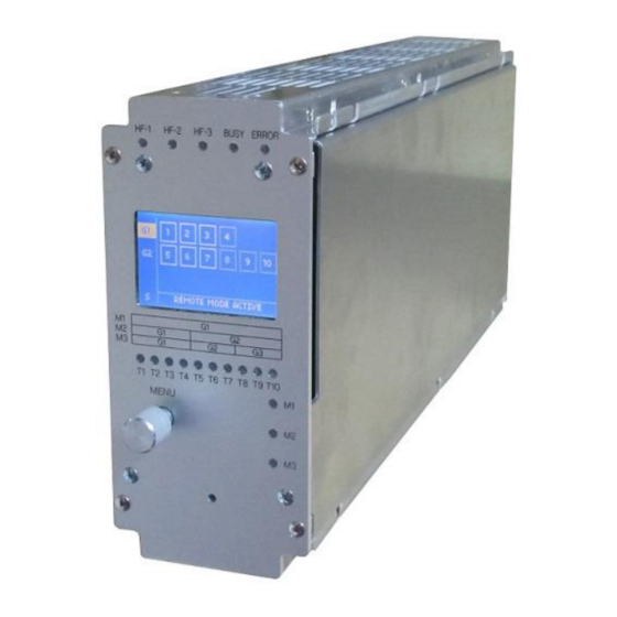
Page 3: Overview
Overview The soniKKs Switchbox is a smart tool that will increase the capacities of your ultrasonic generators by allowing them to operate several transducers, one at a time of course. As you can see on the back panel, the box features 3 input connectors... -
Page 4: Schematics
Schematics Here is a simplified drawing of the internal relays that connect the generators to the outputs. 2014-10-01 soniKKs GmbH - Ultrasonics Technology Doc.nr.: xxxx.xxxx page 4 of 23 Rev.: 1.0... -
Page 5: Menu-Items And Operation
2014-10-01 soniKKs GmbH - Ultrasonics Technology Doc.nr.: xxxx.xxxx page 5 of 23 Rev.: 1.0... -
Page 6: Status Leds
ON: mode 1 is selected (1 generator) M2 - LED ON: mode 2 is selected (2 generators) M3 - LED ON: mode 3 is selected (3 generators) 2014-10-01 soniKKs GmbH - Ultrasonics Technology Doc.nr.: xxxx.xxxx page 6 of 23 Rev.: 1.0... -
Page 7: Navigation Chart
1, 2 or 3 (de-)activate Remote generators transducers Local Language Greetings Display English Contrast Hello German Backlight Logo French Beeper Exit Back to the Switchbox State screen 2014-10-01 soniKKs GmbH - Ultrasonics Technology Doc.nr.: xxxx.xxxx page 7 of 23 Rev.: 1.0... -
Page 8: Screens
In any case, you always have the possibility to enter the settings by selecting the “S” tab and entering the correct password (see the “Password” screen). 2014-10-01 soniKKs GmbH - Ultrasonics Technology Doc.nr.: xxxx.xxxx page 8 of 23 Rev.: 1.0... -
Page 9: Password Screen
Make sure that there is no ultrasonic power on any input of the switchbox before applying the change and during the whole switching process. 2014-10-01 soniKKs GmbH - Ultrasonics Technology Doc.nr.: xxxx.xxxx page 9 of 23 Rev.: 1.0... - Page 10 This screen allows you to choose what will be displayed on startup. You can either select to display the stored logo or a simple “Hello” message. 2014-10-01 soniKKs GmbH - Ultrasonics Technology Doc.nr.: xxxx.xxxx page 10 of 23 Rev.: 1.0...
- Page 11 Push again to set the displayed option and go on to the beeper adjustment. Choose between “On” and “Off”. EXIT Pushing the rotary encoder makes you leave the settings and brings you back to the “Switchbox State” screen. 2014-10-01 soniKKs GmbH - Ultrasonics Technology Doc.nr.: xxxx.xxxx page 11 of 23 Rev.: 1.0...
-
Page 12: Operating The Sonikks Switchbox
Operating the soniKKs switchbox To get started with the soniKKs Switchbox, the first thing you need to determine is how many generators and transducers your application needs. Once you have this information, you can connect the different devices to the switchbox and configure it, before you can actually use it. -
Page 13: Local Output Switching
The connection between your controller and the switchbox can be made via the 15-pole D- SUB socket located on the back panel. The different signals coming to and from the switchbox are the following: 2014-10-01 soniKKs GmbH - Ultrasonics Technology Doc.nr.: xxxx.xxxx page 13 of 23 Rev.: 1.0... - Page 14 Busy Output L: 0V / H: 24V Busy output signal Input Ground reference from the controller +24V Input 24V – 100mA Supply voltage from the controller 2014-10-01 soniKKs GmbH - Ultrasonics Technology Doc.nr.: xxxx.xxxx page 14 of 23 Rev.: 1.0...
-
Page 15: 1.4.2 Remote Output Switching
* the switching time is longer than 230ms for a configuration switching (i.e. changing the number of generators). For an output switching, it is rarely more than 220ms. 2014-10-01 soniKKs GmbH - Ultrasonics Technology Doc.nr.: xxxx.xxxx page 15 of 23... - Page 16 As you can see in the table above, some commands have no effect. Sending such a command to the switchbox will result in an error status. The switchbox will then display “INVALID SELECTION” (see Error Messages). 2014-10-01 soniKKs GmbH - Ultrasonics Technology Doc.nr.: xxxx.xxxx page 16 of 23 Rev.: 1.0...
-
Page 17: Connecting Several Switchboxes In Parallel
Connecting several switchboxes in parallel In remote mode, soniKKs switchboxes offer you the possibility to operate several of them with only one controller. In order to do so, you need to set up the following lines between your controller and the switchboxes: 1 BCD bus (of 4 lines) Several selection lines (“Data Valid”... -
Page 18: Error Messages
The controller sent a switch command while a configuration process was ongoing (and the switchbox was busy). An output switching is only allowed when the switchbox is NOT busy. 2014-10-01 soniKKs GmbH - Ultrasonics Technology Doc.nr.: xxxx.xxxx page 18 of 23 Rev.: 1.0... - Page 19 Ultrasonic power was detected on an input that has no transducer selected. 2014-10-01 soniKKs GmbH - Ultrasonics Technology Doc.nr.: xxxx.xxxx page 19 of 23 Rev.: 1.0...
-
Page 20: Change History
+24V Data Valid min. 200ms Note that the wrong manipulation (red pattern) will cause an error message to occur and the switch command will be ignored. 2014-10-01 soniKKs GmbH - Ultrasonics Technology Doc.nr.: xxxx.xxxx page 20 of 23 Rev.: 1.0... -
Page 21: Maintenance And Care
Damage due to operation by non-qualified staff Damage due to nonobservance of safety regulations or accident prevention regulations Damage due to modifications to the operating manual 2014-10-01 soniKKs GmbH - Ultrasonics Technology Doc.nr.: xxxx.xxxx page 21 of 23 Rev.: 1.0... -
Page 22: Declaration Of Ce Conformity
Ultrasonics Technology GmbH” Manufacturer’s Address: Neuenbürgerstrasse 72 Dobel, GERMANY We, the manufacturer “soniKKs Ultrasonic technology GmbH” declare in our sole responsibility that the upper mentioned RF - Switchbox corresponds to the following EEC directives: EN 50081-1 EN 50082-2 EN 55022... -
Page 23: Imprint
This manual has been prepared with all due care, nevertheless faults and omissions cannot be fully precluded. soniKKs GmbH reserves the right to make changes to the technical data and specifications during the course of further development of the product without given prior notice.
Need help?
Do you have a question about the HFU-D-310 and is the answer not in the manual?
Questions and answers