
Related Manuals for BIO UV O'CLEAR ELITE


Summary of Contents for BIO UV O'CLEAR ELITE
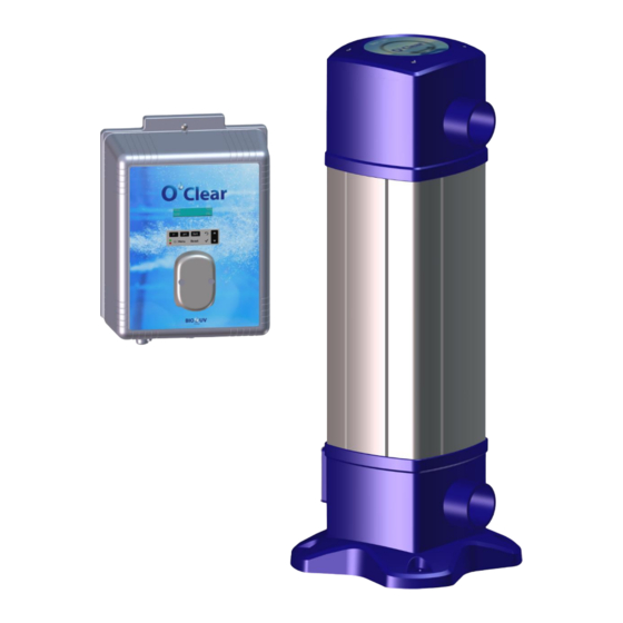
- Page 1 STERILIZER O’CLEAR ELITE INSTALLATION AND MAINTENANCE MANUAL O CLEAR-Elite_(Anglais) - DOC016536 - Ind. A01 - 22/03/2021...
-
Page 2: Table Of Contents
We thank you for choosing a BIO-UV reactor. Our equipment has been designed to give you reliable and safe operation for many years to come. The BIO-UV reactors have been designed for speed and ease of installation. Their design also makes them easy to maintain. Read these instructions carefully in order to optimize the operation of your reactor. - Page 3 G.5. Parameters Menu ............................29 G.5.1. Setting the date and time ........................29 G.5.2. Selecting the display language ....................... 29 G.5.3. Specification of the volume of the pool ....................29 G.5.4. Sensors settings ............................29 G.5.5. Alarms settings ............................30 G.5.6.
-
Page 4: Safety Warnings
A. SAFETY WARNINGS • Switch off the device 30 minutes before any intervention to let the lamp cool down. • The system must not operate without water flow (pumps interlock) Warning: • Never expose yourself to the radiation of the ultraviolet lamp This device when lit. -
Page 5: Symbols Description
• Never dismount the quartz tube sealing washer when the reactor is on load as the quartz tube could be blown out of the reactor with force and injure you. • In case of a microleakage, the reactor must be isolated and drained to perform a maintenance as soon as possible. -
Page 6: Packing List
C. PACKING LIST Solvent weld fitting Ø75 Electronics unit mounting UV reactor Electrical cabinet kit (wall mount, screws and wall plugs) REF: RAC015112 2 x Restrictors 75x63 Saddle REF : RAC015404 Power cable Power cable (in kit) x3 for electronics unit for electrolytic cell 2 x Restrictors 75x50 (2x1/2’’+1x3/4’’) -
Page 7: Technical Characteristics
D. TECHNICAL CHARACTERISTICS UNIT O CLEAR 15 ELITE O CLEAR 25 ELITE REACTOR Material Maximum operating pressure Maximum flow rate (after head losses) m3/h A) Full length 1091 B) Depth C) Fixation spacing D) Service spacing E) Width F) Low connection / Floor Weight Connection type Solvent weld fitting... -
Page 8: Reminders And Tips
E. REMINDERS AND TIPS Given the environment and operation of a swimming pool, it is essential to remember the core rules of the different parameters - water conditions, filtration and water balance - that help to achieve, regardless of the water treatment used, a result in line with our expectations while reducing the contribution of different chemicals and avoiding unpleasant and costly accidents. -
Page 9: Balanced Water Parameters
E.6. Balanced water parameters • The pH indicates the alkalinity or acidity of the water. Maintaining pH 7 (neutral pH) is generally desirable. ❖ If the pH is less than 7: acidic water, aggressive to the skin and the pool liners. ❖... -
Page 10: Installation Guide
F. INSTALLATION GUIDE F.1. Foreword BIO-UV reactors are ready to install, no works is required inside the reactor. • The treatment capacity of the equipment must be appropriate for the volume of the pool to be treated, the number of people using the pool, the presence of nearby equipment (overflow, reflecting pool, slide, etc.) and the weather conditions where the equipment is installed. -
Page 11: Usage Environment
F.2. Usage environment Location Room protected from direct sunlight and bad weather Max altitude From 0 to < 2000m Degree of pollution Overvoltage category Protection class against electric shocks Ambient temperature between 5°C et 40°C Corrosive environment Protect the electrical box from any corrosive emanations (hydrochloric acid vapors, salt…) Install the O’Clear equipment in the equipment room, respecting the 0.1 and 2 safety areas around the volume in accordance with the current installation rules (NF C15100). -
Page 12: O'clear Reactor Installation
F.4. O’Clear reactor installation ➢ For an easier maintenance, we recommend to install a By-pass. ➢ The reactor must be installed in vertical position (water inlet downward) Union Ø75 Downstream valve By-pass valve 250mm Upstream valve ➢ The reactor must be always located on the discharges after the filter. ➢... -
Page 13: Standard Installation
F.5. Standard Installation Discharges Skimmers Pool UV Reactor pH corrector container Heater Pump pH Injection Filter Temperature sensor pH probe Principle diagram, the proportions are not respected NB: There is no contraindication for the installation of the O’Clear reactor before or after the heater. ➢... -
Page 14: Mounting The O'clear Elite Electrical Cabinet Onto A Wall
F.6. Mounting the O’Clear Elite electrical cabinet onto a wall 1. Attach the wall mount to the wall using the screws, washers and wall plugs provided, according to the diagrams below. 2. Hang the electrical cabinet onto the wall mount. REAR VIEW OF THE CABINET FIXING HOOK O CLEAR-Elite_(Anglais) - DOC016536 - Ind. -
Page 15: Installation Of Temperature Sensor/ Saddle Assembly
F.7. Installation of temperature sensor/ saddle assembly 1) Mount the saddle on the pipe, as shown in the image opposite. Note : use the 3/4’’ saddle, not the 1/2’’ one 2) Drill the top of the pipe through the hole of the saddle (see arrow opposite), taking care not to damage the tapping. - Page 16 1) Mount the saddle on the pipe, as shown in the image opposite. 2) Drill the top of the pipe through the hole of the saddle (see arrow opposite), taking care not to damage the tapping. 3) Check that the probe bulb is properly immersed in the solution inside the storage vial. If this is not the case: a) Remove the storage vial from the probe (see photo below), and keep it for wintering.
-
Page 17: Installing The Ph Injection Heat Contactor
F.9. Installing the pH injection heat contactor 1) Mount the saddle on the pipe, as shown in the image..A.. Note : use the 1/2’’ saddle, not the 3/4’’ one 2) Drill the top of the pipe through the hole of the saddle (see arrow on the photo.A.), taking care not to damage the tapping. -
Page 18: Instructions For Electrical Connections
F.10. Instructions for electrical connections IMPORTANT : • Connections must be made by a qualified technician. • A residual current device (RCD) not exceeding 30mA must be present and a fuse or a thermal breaker should be installed on the device power supply. •... -
Page 19: Wiring To The Filtration Unit
Cell : Connection for the electrolytic cell using the corresponding power cable. Lamp : UV lamp cable gland. : Power cable connection for electronics unit (220 V - 50/60 Hz). Permanently connect the electronics unit to the electrical unit, by linking it to the filtration pump contactor. -
Page 20: Connection Of The Electrolysis Cell
b) Special case A contactor with an unpowered coil: 1. Use a relay (not provided) to : • - Obtain a voltage identical to that of the coil • - Accept at least 5 amps on its contacts. 2. Connect the O Clear electrical cabinet with the relay as shown below : O Clear Elite electrical cabinet Filtration unit... -
Page 21: Installation Of The Lamp Cable In The Reactor
F.10.4. Installation of the lamp cable in the reactor Unscrew the 4 cover screws using a Phillips screwdriver then remove the cover. Insert the lamp cable connector through the free hole on the upper part of the reactor Fit the cable gland Pass the connector through the nut and slide the nut until the nut is in contact with the cable gland Screw the nut on the cable gland, tightening normally. -
Page 22: Use Of The O'clear Elite Cabinet
G. USE OF THE O’CLEAR ELITE CABINET G.1. Description G.1.1. Overview Screen Keypad LEDs Peristaltic pump G.1.2. Keypad COMMAND FUNCTION • Switching on the electronics unit. → A few minutes after switching on, production starts automatically. • Switching off the electronics unit (press and hold). →... -
Page 23: Leds
G.1.3. LEDs LEDs Colour Status Meaning Green Continuously on Production in progress Continuously on Electronics unit powered off, or wintering mode activated Flashing Alarm activated G.1.4. Setting the production setpoint The electrolysis production setpoint can be adjusted from the main screen. Electrolysis Menu Specific instructions... -
Page 24: Screen Menus Navigation
G.2. Screen menus navigation Note : This diagram includes all options: empty container, Bluetooth, external control, flow, Modbus, salt/temperature. O CLEAR-Elite_(Anglais) - DOC016536 - Ind. A01 - 22/03/2021 Copyright BIO-UV Marque, Modèles et Brevets déposés - Produits exclusifs Page 24... -
Page 25: Electrolysis Menus
G.3. Electrolysis Menus G.3.1. Boost Mode Boost mode : - sets the production setpoint up to 125 %, for a fixed period. - can be manually stopped at any time. - can be used when chlorine is urgently needed. Boost mode cannot replace a conventional shock treatment in cases of water not fit for bathing. It is a preventive mode, not curative. -
Page 26: Setting The Inversion Frequency Of The Current Supplying The Cell
G.3.3. Setting the inversion frequency of the current supplying the cell Current inversion aims to prevent scale deposits on the cell. Current inversion must be set following the table below in order to ensure that the cell continues to operate correctly in the long term. -
Page 27: Ph Regulation Menu
G.4. pH Regulation Menu G.4.1. Manual injection Possible Menu Functions Default setting Instructions settings • To start injecting : Confirm the duration setting. • Priming (The peristaltic pump is running, peristaltic pump and and a timer countdown is From filling semi-rigid displayed in real time.) seconds to 10... -
Page 28: Setting The Ph Setpoint
6) Navigate through the menus following the instructions below : pH Regulation Calibration pH Calibration → Insert the probe into the pH 7 calibration solution, then wait a few minutes. Solution pH Calibration → Do not touch the probe. In Progress (Wait a few seconds) pH Calibration →... -
Page 29: Parameters Menu
G.5. Parameters Menu G.5.1. Setting the date and time Menu Possible settings Default setting Parameters Day / Month / Year 01/01/01 Date XX/XX/XX Parameters Hour / Minute random Time XX:XX G.5.2. Selecting the display language Menu Possible settings Default setting •... -
Page 30: Alarms Settings
Specific Sensor activated Configuration Production pH regulation display Open cover Maintained Cover Closed cover Divided by 5 Cover Command activated Maintained Maintained External command Command not activated Stopped Sufficient flow Maintained Flow Alarm Zero flow Stopped Flow Stopped Alarm Empty container Maintained pH can empty Empty container... -
Page 31: Display Parameters
G.5.9. Display parameters • If display flashing : information awaiting confirmation, or alarm activated. • If display solid : confirmed or read-only information. DEFAULT DISPLAY Setting via the MEANING « Overview Parameters - » menu Display Production setpoint The point just after « »... -
Page 32: Auxiliary Menu
G.7. Auxiliary Menu G.7.1. “UV rate” Parameter (Aux. Rate) → Allows to set the percentage of daily UV lamp operating time regarding the total filtration time of the previous day. Menu Possible settings Default setting Auxiliary From 0 to 100%, in increments of 1 100% Aux. -
Page 33: Maintenance " Parameter
G.7.4. « Maintenance » Parameter → Operating time: Indicates the total operating time of the UV lamp in hours (over the 13000h of lamp life). If the ballast is faulty (the "UV lamp pb” alarm is active), this time does not increase because the lamp is inactive or disconnected. -
Page 34: Safety
G.9. Safety G.9.1. Wintering mode • Wintering mode : - is activated by default. - starts automatically as soon as the water temperature drops below 15°C. • When wintering mode is on : - The message « » is displayed. Low Temp Mode - Production is stopped. -
Page 35: Important Precautions Regarding The Peristaltic Pump
IMMEDIATE AUTOMATIC OPTION TO MESSAGE ACTION DEACTIVATE DISPLAYED VIA THE MENU CAUSE CHECKS AND REMEDIES / FAULT Stopping Stopping pH « Parameters - DETECTED production regulation » Alarms Loss of communication between the control Alarm Com. board and the power Contact a professional. -
Page 36: Pool Preparation
H. POOL PREPARATION H.1. For a new pool or new water ➢ After filling (using water from the mains network), check the cleanliness of the skimmers and filter, perform a shock dose of 35% hydrogen peroxide (active oxygen) of 1L / 10 m3 to complete the cleaning process (with the filtration turned on). -
Page 37: Checks Before Commissioning
I. CHECKS BEFORE COMMISSIONING ➢ Check the conformity of the electrical connection in the filtration unit. ➢ Check UV lamp is well connected. ➢ Check that the electrolysis cell connections are correctly positioned vertically as indicated below Electrode connections must be aligned vertically ➢... -
Page 38: Starting Up
J. STARTING UP When switching on the electronics unit for the first time, basic parameters should be set: • Language : ENGLISH • Volume : from 10 to 200 m3 (regarding the pool volume), in increments of 10 • / Month / Year) Date : current date (format : Day •... -
Page 39: Four Essential Steps
K. FOUR ESSENTIAL STEPS K.1. Water balance Increase pH with some pH must be maintained between pH 7 and 7.4 Decrease pH with some TAC must be maintained between 10 and 15 Use some TAC+ °F K.2. Filtration •... -
Page 40: Maintenance
L. MAINTENANCE Any operation on the device must be carried out by qualified and skilled personal. The device must be disconnected from the electrical network before any intervention. Please cut off main power supply with breaker that protect your equipment. The handling of UV lamps and quartz sleeves must absolutely be done with protective gloves to avoid leaving fingerprints which could affect the quality of UV emissions and to protect the hands in the event of glass breakage. - Page 41 Make sure that the UV lamp is cooled enough before handle it. Remove the lamp (use the connector if necessary) and lay it on a clean and smooth surface. Carry out this operation carefully without touching the glass of the lamp with the hands Do not drop the lamp in the quartz sleeve as it could break and damage the quartz.
-
Page 42: Quartz Sleeve Dismounting
L.2. Quartz sleeve dismounting Every year you must check that the quartz sleeve has not became opaque due to scale deposits. It should be completely transparent not to reduce the UV radiations. The sterilizer MUST be POWERED OFF, BY-PASSED and fully DRAINED. - Page 43 While remaining well aligned with the axis, introduce the quartz sleeve into the reactor to its guide at the bottom of the reactor. Wearing clean gloves, position the quartz to into the bottom of its holder by using your finger inside the sleeve. A flashlight can help you to see the holder through the quartz.
-
Page 44: Maintenance Of The Electrolytic Cell
L.3. Maintenance of the electrolytic cell The auto-clean function helps prevent scale deposits on the electrolytic cell. However, if scale builds up despite this, carry out a manual cleaning: 1) Turn off the equipment (reactor powered off) and drain the reactor; 2) Disconnect the electrode then dismount it in order to check for signs of scale;... -
Page 45: Shutdown For Extended Periods / For Winter
L.4. Shutdown for extended periods / for winter L.4.1. Procedure 1) Turn off the complete filtration equipment. 2) Drain the pH injection heat contactor. → Never store the probe in distilled water. → Never touch the bulb of the probe. 3) Equip yourself with: the storage bottle initially mounted on the probe, the stopper supplied,... -
Page 46: Maintenance Of The Ph Regulation
L.5. Maintenance of the pH regulation L.5.1. pH probe → Ensure that the bulb of the pH probe is always immersed, either in water or in a suitable KCl solution. → Periodic maintenance to be carried out: twice/year, each time the equipment is put back into service, each time the probe is changed. -
Page 47: Uv Reacgtor Blown Up View And Spare Parts
M. UV REACGTOR BLOWN UP VIEW AND SPARE PARTS REFERENCES REFERENCES DESIGNATION O’CLEAR 15 ELITE O’CLEAR 25 ELITE Screw CLZ M4X30 VIS001546 VIS001546 Connector ELE002603 ELE002603 UV lamp LPE000004 LPE000005 Screw FHC M4X20 VIS000031 VIS000031 Upper bracket (sealing washer) USI014441 USI014441 Quartz sleeve QUA000017... -
Page 48: Recycling
N. RECYCLING N.1. Lamps and electronic components In accordance with WEEE Directive 2012/19 / EU on electrical and electronic equipment waste, electronic components and old lamps must be collected by a specific process and must not be disposed of in a conventional waste bin. -
Page 49: Warranties
O. WARRANTIES Units in the BIO-UV range are guaranteed subject to the following conditions: 5 years for the PVC reactor. Warranties exceptions: Damages caused by overpressure (water hammer) Overtaking of the maximum operating pressure No respect of the installation recommendations A reactor that has run without water Damages caused by freezing.
Need help?
Do you have a question about the O'CLEAR ELITE and is the answer not in the manual?
Questions and answers