Advertisement
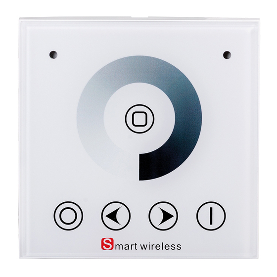
2.4G RF touch dimming wall panel, 1 zone
DESCRIPTION
2.4G SMART light control system includes series of RF remotes, dimmable constant current LED drivers
and dimmable constant voltage LED power supply. The LED light can be adjusted with multi zone control
function (single zone or overall zones control).
SSW1Z is an RF touch remote that can control only a group of already paired drivers and power supplies
for LED light from the series – SSD13300, SSD40850, SSD1216.
TECHNICAL DETAILS
•
Working voltage: 220-240 V AC/ 50-60 Hz
•
Number of control zones: 1
•
Frequency: 2.4 GHz
•
Index of protection: IP20
•
Remote distance: up to. 20 m
•
Dimensions: 87/87/33 mm
•
Working temperature: -10⁰ C ÷ +40⁰ C
•
Warranty: 2 years
KEYS FUNCTION
Key
Function
ON
ON in any time
OFF
OFF in any time
Mode
100% brightness
Decrease light brightness, long press
Brightness -
continuously
Increase light brightness, long press
Brightness +
continuously
Touch any dimming brightness which you
Dimming Ring
want
RF CODE SETTING
Matching Operation
1. Connect the driver with load LED (Without power on).
2. Pressing Mode Key and hold on, power on the driver, the load LEDs will be 50% brightness as
responding to enter match code state.
Model № SSW1Z
4 4
Advertisement
Table of Contents

Summary of Contents for UltraLux SSW1Z
- Page 1 LED power supply. The LED light can be adjusted with multi zone control function (single zone or overall zones control). SSW1Z is an RF touch remote that can control only a group of already paired drivers and power supplies for LED light from the series – SSD13300, SSD40850, SSD1216.
- Page 2 3. Continuously to press the key On for 3 times within 5 seconds the brightness of LEDs will change from 25%, 10%, after the third press, the light will blink 3 times and then go to the state where it was last.
- Page 3 With a standard mounting box for plasterboard After connecting the RF switch 1. Mount the metal base and the box using to the power supply, the mounting screws to lock the console mount it to the metal base. to the plasterboard.
Need help?
Do you have a question about the SSW1Z and is the answer not in the manual?
Questions and answers